The significant feature of semi-physical simulation is "hardware in the loop". Compared with traditional digital simulation, since the physical model participates in the entire simulation process in the test, each link in the test process is closer to the real state, the credibility and reference value of the test results are higher, and it is closer to reality than digital simulation, which is an ideal research method. The author has designed an aircraft brake control system simulation test platform to provide a more effective test platform for the experimental research of aircraft brake control systems.
1 System hardware composition
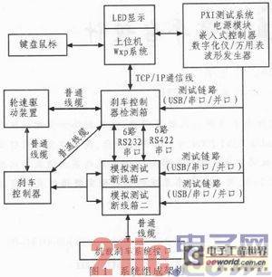
The test platform takes into account both the simulation and testing of the aircraft brake system inside and outside the field. The main components include: host computer, brake controller test box, simulation test disconnection box 1, simulation test disconnection box 2, brake system detection controller, wheel speed drive box and power box. The equipment is fully functional. The system composition architecture is shown in Figure 1.

The main functions of the equipment in the system are as follows:
1) Host computer: Establish a model in the Matlab/Simulink environment, complete the program compilation, generate an executable file, and download it to the slave computer.
2) Slave computer: Communicate with the host computer through I/O devices, write the host computer program, analyze the output signals one by one, complete the data analysis and calculation in real time, and forward the signal to the PXI test equipment through the corresponding test link interface. The signal generated by the wheel speed drive circuit drives the aircraft wheel to rotate at the specified wheel speed through the signal line.
3) Wheel speed drive box: Complete the simulation of the inner field wheel speed drive: simulate the wheel speed drive signal during the inner field test, adjust the control signal to make the linear motor drive the wheel speed to the corresponding speed according to the control signal, and collect the corresponding signal from the sensor to the host computer, which plays the role of simulating the rotation of the aircraft wheel.
4) Finished product load simulation: simulate the input and output signals
of the airborne brake finished product and the front wheel turning finished product. 5) Simulation test disconnect box: accurately detect and transmit the signals that need to be controlled, simulated, and tested through the on and off of the jumper switch.
6) Test link: integrated PXI multifunctional test system, providing signal source, generating any frequency signal of 3Hz~12KHz, stepping 1Hz, 4ms refresh, program-controlled power supply signal, etc., and completing the acquisition and processing of various system signals through oscilloscope, multimeter and other test equipment.
7) Power supply box: completes the conversion of power supply, converting the input AC220V into DC linear positive and negative 15V and standard DC10V, DC28V, DC24V output.
[page]
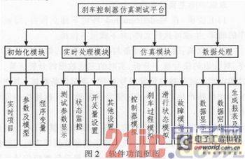
The brake controller test software must complete the system parameter settings, provide data acquisition, display, storage and playback functions, detect the controller status, the comprehensive performance of the brake system and the performance indicators of each accessory, and simulate the brake controller model. To meet the system requirements and facilitate user use, the software system must be reliable, scalable and applicable. The test software adopts a modular design, including initialization module, real-time interface module, simulation module and data processing module. The functional module structure diagram is shown in Figure 2.

2.1 Development Environment
This test system uses LabWindows/CVI2009 as the interface development platform. The software provides many graphical controls to make the operation interface vivid and easy for users to operate, observe simulation results, save and replay simulation data, etc. It also provides a wealth of signal processing functions, network support, multi-threading and dynamic link libraries, and can develop cross-platform application software that supports multi-threading and network transmission.
2.2 Description of some software function modules
When users use this test system, they first enter the user login interface and enter the correct user name and password before they can log in to use the system, which ensures the security of the test system database. The user login interface is shown in Figure 3.

After the user enters the correct username and password, he/she enters the system initialization module interface.
[page]
2.2.1 Initialization moduleThe main functions of the initialization module are:
1) Setting the experimental project, test time, file storage path, operator, etc.;
2) Setting the parameters of each acquisition signal and the simulation model mode;
3) Initialization of program variables, mainly the initialization of the global variables inside the program and the computer port, to ensure the stability and accuracy of the data when the program is running.
2.2.2 Detailed design of the initialization module
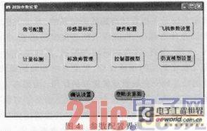
After logging into the system, the user enters the system parameter configuration interface to set and calibrate the system parameters before testing. The parameter configuration interface is shown in Figure 4.

Click the "Aircraft Parameter Settings" button on the interface to enter the aircraft parameter settings interface. The upper left corner of the interface is for aircraft parameter settings, the upper right corner is for landing gear parameter settings, and the lower part of the interface can be used to set the friction surface pair, brake friction coefficient settings, and runway model. After the settings are completed, click the "Settings Completed" button to exit the interface, return to the initial interface, and complete the initialization of other parameters. The aircraft parameter settings interface is shown in Figure 5.

Before using the sensor, the user must calibrate the sensor. Click the "Sensor Calibration" button to enter the sensor calibration interface, as shown in Figure 6.
[page]
The upper left of the sensor calibration interface displays the computer sampling value in a chart, the upper right displays the sensor's zero bias and gain in text form, the lower left displays the computer sampling value and actual value of the wheel speed sensor and pressure sensor, and the lower right displays the calibration result.
2.2.3 Real-time interface module
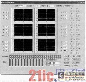
After initializing the system parameters, the user enters the real-time detection interface of the test system, as shown in Figure 7.

The main function of the main interface is to display the data of the experiment process and the information of the current state signals in real time. The left side of the main control panel displays the numerical value of the test data. The important data that the user needs to pay special attention to is displayed in the form of a data curve using the chart in the middle of the panel. The right side of the panel displays the test data value. The switch on the far right of the panel is used by the user to turn on and off the switch quantity. The LED light below the panel is used to display the status of each D/I signal. If it is normally turned on, it is displayed in green. If a fault occurs, it is displayed in red. If it is closed, it is displayed in gray. The lower progress bar is used to display the simulated D/A quantity. The text box in the lower right corner is used to display in real time whether the various components of the brake system are working well during the simulation, so that the user can observe the performance of the brake system in real time. The buttons in the lower right corner provide various options for experimental operations. For example, clicking the "Data Playback" button can display the saved data in the form of a curve, which is convenient for users to find the rules of the test data.
3 Conclusion
This test platform is a semi-physical simulation test platform. Part of the hardware of the brake system can be connected to the circuit of the test system. When conditions permit, as many physical objects as possible are connected to the simulation system to replace the corresponding part of the simulation model. This not only greatly improves the realism of the simulation, but also solves the problem of system modeling. Compared with physical simulation, this test system has low investment and high efficiency. At the same time, it is closer to reality than traditional digital simulation. It is an ideal test method and can provide a real and effective experimental platform for experimental research on aircraft braking systems.
Previous article:Complete, low-cost, software-programmable ohmmeter measures resistance in the micro-ohm range
Next article:The Principle and Application of Analog Multiplier ADL5391
- Popular Resources
- Popular amplifiers
- New IsoVu™ Isolated Current Probes: Bringing a New Dimension to Current Measurements
- Modern manufacturing strategies drive continuous improvement in ICT online testing
- Methods for Correlation of Contact and Non-Contact Measurements
- Keysight Technologies Helps Samsung Electronics Successfully Validate FiRa® 2.0 Safe Distance Measurement Test Case
- From probes to power supplies, Tektronix is leading the way in comprehensive innovation in power electronics testing
- Seizing the Opportunities in the Chinese Application Market: NI's Challenges and Answers
- Tektronix Launches Breakthrough Power Measurement Tools to Accelerate Innovation as Global Electrification Accelerates
- Not all oscilloscopes are created equal: Why ADCs and low noise floor matter
- Enable TekHSI high-speed interface function to accelerate the remote transmission of waveform data
- Intel promotes AI with multi-dimensional efforts in technology, application, and ecology
- ChinaJoy Qualcomm Snapdragon Theme Pavilion takes you to experience the new changes in digital entertainment in the 5G era
- Infineon's latest generation IGBT technology platform enables precise control of speed and position
- Two test methods for LED lighting life
- Don't Let Lightning Induced Surges Scare You
- Application of brushless motor controller ML4425/4426
- Easy identification of LED power supply quality
- World's first integrated photovoltaic solar system completed in Israel
- Sliding window mean filter for avr microcontroller AD conversion
- What does call mean in the detailed explanation of ABB robot programming instructions?
- STMicroelectronics discloses its 2027-2028 financial model and path to achieve its 2030 goals
- 2024 China Automotive Charging and Battery Swapping Ecosystem Conference held in Taiyuan
- State-owned enterprises team up to invest in solid-state battery giant
- The evolution of electronic and electrical architecture is accelerating
- The first! National Automotive Chip Quality Inspection Center established
- BYD releases self-developed automotive chip using 4nm process, with a running score of up to 1.15 million
- GEODNET launches GEO-PULSE, a car GPS navigation device
- Should Chinese car companies develop their own high-computing chips?
- Infineon and Siemens combine embedded automotive software platform with microcontrollers to provide the necessary functions for next-generation SDVs
- Continental launches invisible biometric sensor display to monitor passengers' vital signs
- [Review of Arteli Development Board AT32F421] 6. Further study of EC11 encoder
- Help pic16f1937 control servo routine
- TMS320DM8148 floating point DSP C674x + ARM Cortex-A8RGMIICAN bus interface
- GD32E231 DIY Competition (3) GD32E231C driving OLED (128X32)
- Internal Hardware Resources of PIC 16F84 Microcontroller (Part 2)
- 13264 LCD module
- Used NUCLEO-F413ZH for sale
- MF RC500
- Looking for domestic brushless motor control chip?
- Questions about second-order SK low-pass filter

 HA3-2505-5


 京公网安备 11010802033920号