Translated from Google Blog, published by Artem Dementyev, Hardware Engineer at Google Research
As wearable and handheld devices decrease in size, haptics have become an increasingly important feedback channel, whether through silent alarms or the subtle "click" sensation of pressing a button on a touchscreen. Touch feedback is ubiquitous in nearly all wearables and mobile phones, and is typically implemented via linear resonant actuators (LRAs), which are small linear motors that use resonance to provide a powerful tactile signal in a small package. However, the touch and pressure sensing required to activate haptic feedback often depends on additional, standalone hardware, which increases the price, size, and complexity of the system.
In the paper “Haptics with Input: Back-EMF in Linear Resonant Actuators for Touch, Pressure, and Environmental Awareness,” presented at ACM UIST 2020, we demonstrated that widely used LRAs can sense a variety of external information such as touch, tap, and pressure sensing in addition to being able to convey information about contact with skin, objects, and surfaces. We achieved this using off-the-shelf LRAs by multiplexing the excitation with short pulses of customized waveforms designed to sense using the back-EMF voltage. We demonstrated the potential of this approach to express discrete buttons and vibrotactile interfaces, and showed how this approach can bring rich sensing opportunities to integrated haptic modules in mobile devices, increasing sensing capabilities with fewer components. Our technique is likely compatible with many existing LRA actuators, as they already employ back-EMF detection to automatically adjust the vibration frequency.

Different Types of LRAs
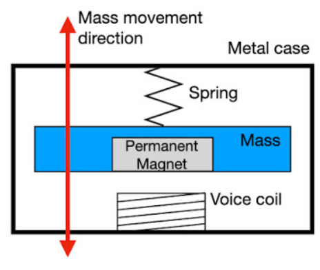
The back EMF principle in an LRA is that there is a magnet inside the LRA housing, attached to a very small object, both of which are free to move on springs. The magnet moves in response to the excitation voltage introduced by the voice coil. The movement of the oscillating mass generates a back EMF, which is a voltage proportional to the rate of change of magnetic flux. A larger oscillation speed will produce a larger back EMF voltage, while no movement will produce a zero back EMF voltage.

LRA Principle
Active Back-EMF Sensing
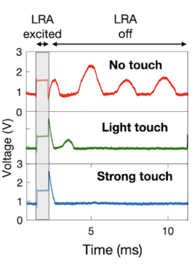
When a vibration occurs during contact with or against an LRA, energy is dissipated into the contact object, changing the velocity of the internal mass. This works well for soft materials that deform under pressure, such as the human body. For example, a finger vibrating close to an LRA will absorb varying amounts of energy depending on the contact force. By driving the LRA with a small amount of energy, we can measure this phenomenon using the back-EMF voltage. Since sensing with back-EMF behavior is an active process, the key to making this work is to design a custom, non-resonant driver waveform that can sense continuously while minimizing vibration, sound, and power consumption.

Touch and pressure sensing on LRA
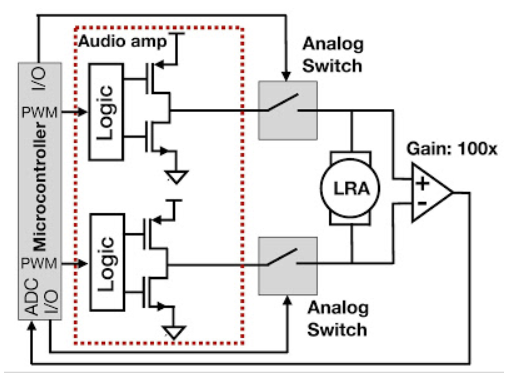
When we measure the back EMF from the floating voltage between the two LRA leads, we need to disconnect the motor driver briefly to avoid interference. When the driver is disconnected, the mass is still oscillating inside the LRA, generating an oscillating back EMF voltage. Because commercial back EMF sensing LRA drivers do not provide raw data, we designed a custom circuit that is able to pick up and generate the back EMF voltage. We also generated customized drive pulses to minimize vibration and energy loss.

Simplified schematic of the LRA driver and back-EMF measurement circuit for active sensing

After exciting the LRA with a short drive pulse, the back-EMF voltage fluctuates due to the continuous fluctuation of the mass on the spring (top, red line). When pressed by a finger, the back-EMF signal changes depending on the pressure applied (center/bottom, green/blue lines).
Application
LRAs for phones behave the same whether they are placed on a table, on a soft surface, or handheld. This can cause problems, as the phone may slide off a glass table or make unwanted vibrating sounds due to vibrations. Ideally, an LRA on a phone would automatically adjust to its environment. We demonstrated sensing using LRA back-EMF technology by connecting directly to a Pixel 4’s LRA and then classifying whether the phone is being handheld, placed on a soft surface (foam), or placed on a table.

Perceive phone environment
We also present a prototype that demonstrates how LRAs can be used as combined input/output devices in portable electronics. We connected two LRAs, one on the left side of the phone and one on the right side of the phone. These buttons provide tap, touch, and pressure sensing. They also provide haptic feedback once a touch is detected.

Press the side button
There are many wearable haptic aids such as sleeves, vests, and bracelets. In order to transmit tactile feedback to the skin with consistent pressure, the correct pressure must be applied; it cannot be too loose or too tight. Currently, the usual way is through manual adjustment, which can cause inconsistency and lack of measurable feedback. We show how to use LRA back-EMF technology to continuously monitor the bracelet device being worn and prompt the user if it is too tight, too loose, or just right.

Wristband sensor
Evaluation of LRA
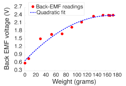
LRAs work well as pressure sensors because they have a quadratic response to the amount of force during a touch. Our approach works for all five off-the-shelf LRA types we evaluated. With typical power consumption of just 4.27 mA, providing sensing all day would only reduce the battery life of a Pixel 4 phone from 25 hours to 24 hours. Power consumption can be greatly reduced by using low-power amplifiers and employing active sensing only when needed (e.g., when the phone is active and the user is interacting).

When pressure is applied with a finger, the back EMF voltage changes
The challenge of active sensing is to minimize vibrations so they are not felt when touched and no audible sound is emitted. We optimized active sensing to produce only 2 dB of noise and 0.45 m/s2 peak-to-peak acceleration, which is barely perceptible to the finger and quiet compared to the normal 8.49 m/s2.
Future Work and Conclusion
In the future, we plan to explore other sensing techniques, perhaps measuring current could be another approach. Similarly, using machine learning could potentially improve sensing and provide more accurate classification of complex back-EMF patterns. Our approach could be further developed to enable closed-loop feedback between the actuator and sensor, allowing the actuator to provide the same force regardless of external conditions.
We believe this work opens new opportunities to provide rich interactions and closed-loop feedback tactile actuators using existing hardware.
Acknowledgements
This work was done by Artem Dementyev, Alex Olwal, and Richard Lyon. Thanks to Mathieu Le Goc and Thad Starner for feedback on this article.
Previous article:What are the requirements of the oil industry for pressure sensors?
Next article:ROHM develops compact, high-precision pressure sensor IC with IPX8 waterproof rating
- Popular Resources
- Popular amplifiers
- Infineon's PASCO2V15 XENSIV PAS CO2 5V Sensor Now Available at Mouser for Accurate CO2 Level Measurement
- Milestone! SmartSens CMOS image sensor chip shipments exceed 100 million units in a single month!
- Taishi Micro released the ultra-high integration automotive touch chip TCAE10
- The first of its kind in the world: a high-spectral real-time imaging device with 100 channels and 1 million pixels independently developed by Chinese scientists
- Melexis Launches Breakthrough Arcminaxis™ Position Sensing Technology and Products for Robotic Joints
- ams and OSRAM held a roundtable forum at the China Development Center: Close to local customer needs, leading the new direction of the intelligent era
- Optimizing Vision System Power Consumption Using Wake-on-Motion
- Infineon Technologies Expands Leading REAL3™ Time-of-Flight Portfolio with New Automotive-Qualified Laser Driver IC
- Qorvo® Selected as Key Supplier of Wi-Fi 7 FEM for MediaTek Dimensity 9400
- LED chemical incompatibility test to see which chemicals LEDs can be used with
- Application of ARM9 hardware coprocessor on WinCE embedded motherboard
- What are the key points for selecting rotor flowmeter?
- LM317 high power charger circuit
- A brief analysis of Embest's application and development of embedded medical devices
- Single-phase RC protection circuit
- stm32 PVD programmable voltage monitor
- Introduction and measurement of edge trigger and level trigger of 51 single chip microcomputer
- Improved design of Linux system software shell protection technology
- What to do if the ABB robot protection device stops
- Detailed explanation of intelligent car body perception system
- How to solve the problem that the servo drive is not enabled
- Why does the servo drive not power on?
- What point should I connect to when the servo is turned on?
- How to turn on the internal enable of Panasonic servo drive?
- What is the rigidity setting of Panasonic servo drive?
- How to change the inertia ratio of Panasonic servo drive
- What is the inertia ratio of the servo motor?
- Is it better for the motor to have a large or small moment of inertia?
- What is the difference between low inertia and high inertia of servo motors?
- 【Recruitment】RF Engineer
- [NXP Rapid IoT Review] Hello LED
- 【STM32WB55 Review】2# Use of STM32WB development board
- Recruitment: Power supply R&D technician (assistant, apprentice)
- TMS320F28335 Study Notes - Clock
- Four-axis special PID parameter tuning method and principle
- [Hua Diao Experience] 10-line empty board hardware control pinpong library series test (Part 3)
- Can this schematic control the LDO enable and disable through transistors?
- Huada HC32F4A0 replaces STM32F405/407/427 series chips--simple replacement comparison
- Why can byte addresses overlap with bit addresses?

 TC1025EOA


 京公网安备 11010802033920号