This article is compiled from the official blog of bluetooth.com
Bluetooth-enabled devices are capable of highly reliable communications even in the most challenging situations. Bluetooth technology is designed with reliability in mind at every layer and uses a variety of techniques to reduce the likelihood of interference.
Recently, Martin Woolley, the developer relations manager for the Bluetooth Special Interest Group (SIG), published a paper exploring the reliability of Bluetooth technology. In this in-depth look at Bluetooth reliability, Woolley explains how Bluetooth technology establishes reliable connections despite the inherent unreliability of the radio.
The following is the abstract of the paper
Creating Reliability from an Unreliable Foundation
Bluetooth technology uses radio, and radio is unreliable, but Bluetooth communications work very well, so how do we explain this apparent contradiction? The answer lies in various aspects of the design of the Bluetooth communication system, including its use of radio and its protocol.
Bluetooth technology is a modular system and multiple stack configurations are possible.
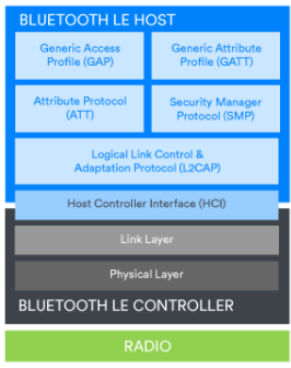
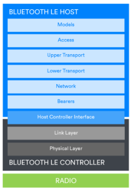
Figure: Stack configuration to support Bluetooth mesh
Smartphones and connected peripherals will include a Bluetooth Low Energy (LE) controller with a host component that supports the Generic Access Profile (GAP) and Generic Attribute Profile (GATT) as well as protocols such as the Attribute Protocol (ATT) and the Security Manager Protocol (SMP).
A Bluetooth Mesh network will also contain a Bluetooth LE controller, but the host portion will contain the layers of the Bluetooth Mesh network stack.
Regardless of the stack configuration, each layer has well-defined responsibilities and methods for passing data to adjacent layers above and below. Features of Bluetooth technology that mitigate or reduce the likelihood of certain types of potential reliability issues exist in various parts of the stack. Some of these mechanisms apply to all possible uses of Bluetooth technology, while some of them apply only to specific situations.
Generally applicable features and mitigation techniques
We will first preview the reliability enhancements to Bluetooth that are generally applicable to all situations. The diagram shows the Bluetooth air interface packet.
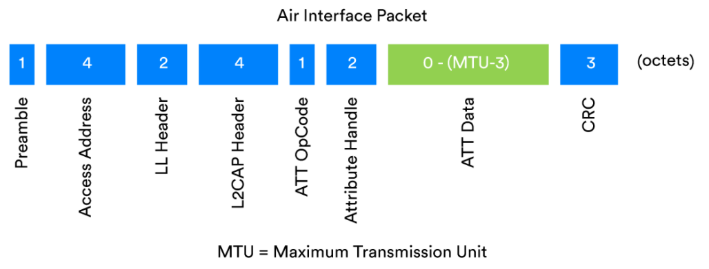
Example of a Bluetooth packet containing an ATT PDU
Bluetooth modulation scheme
The reliability of Bluetooth technology starts with the most fundamental issues concerning how the radio is used as a carrier of digital data. In the Bluetooth stack, these issues are handled in the physical (PHY) layer.
One of the main issues that the physical layer must deal with is being able to identify Bluetooth radio transmissions and correctly extract the data encoded into the signal. This is absolutely fundamental on the road to reliability.
Radio is a simulated physical phenomenon. Physicists usually model radio signals in terms of radio waves. Radio waves are electromagnetic energy and have a set of basic properties, including amplitude, wavelength, and frequency. The strategy of using these basic properties of waves to encode information in some way is called a modulation scheme. There are many modulation schemes, some use changes in the amplitude of the signal; some use changing amplitudes; some use radio phase to encode information; and some use changes in frequency.
When reliability is an important design goal for a radio communication system, some modulation schemes are better than others. Amplitude-based modulation schemes are somewhat susceptible to interference caused by noise, while frequency-based schemes are less susceptible in this regard.
Basic wave characteristics
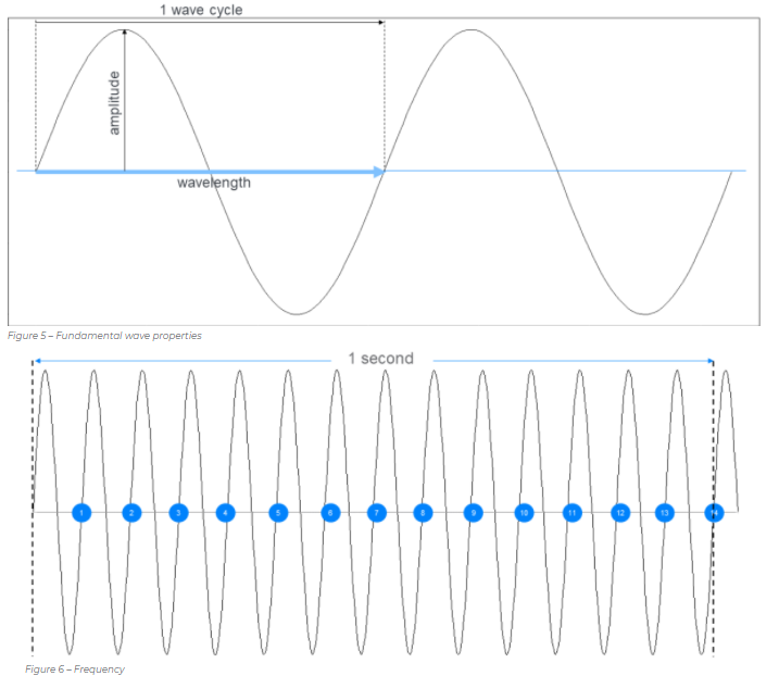
Frequency characteristics
Bluetooth technology uses a special binary frequency shift keying modulation scheme called Gaussian frequency shift keying (GFSK). This is a binary modulation scheme because each symbol represents only one bit with a value of zero or one.
Binary frequency shift keying encodes digital data by selecting a center frequency, called a carrier, and then shifting it up a given frequency deviation to represent a 1 or shifting it down by the same frequency deviation to represent a 0. The number of allowables is specified in the Bluetooth core specification, depending on the symbol rate selected, which is 1 or 2 megasymbols per second (Msym/s) in Bluetooth LE. For a symbol rate of 1 Msym/s, the specified minimum frequency deviation is 185 kHz, while for faster symbol rates, the specified minimum frequency deviation is 370 kHz. Careful selection of these values can help reliably identify the encoded 1s and 0s.
By definition, frequency shift keying (FSK) modulation schemes involve frequency changes every time the symbol value changes. Sudden changes in frequency can generate noise and interference. Furthermore, in practical circuits, there is the possibility of spectral leakage, where the signal inadvertently spills over to other frequencies, making it more difficult to decode it at the receiver.
Bluetooth technology reduces interference by using an advanced FSK modulation scheme. The Gaussian aspect of GFSK modifies the standard FSK method by including a filter that makes the frequency transitions smoother, resulting in less noise and a narrower spectrum width, which reduces interference with other frequencies.
Leading
The first Bluetooth LE packet in all Bluetooth LE packets is called a preamble. It is 8 bits long and contains an alternating pattern of binary 1s and 0s. Its purpose is to provide the receiver with information that can be used to find the frequencies used to encode the digital 1s and 0s in the rest of the packet. It can also be used by the radio's automatic gain control to optimize signal strength. Accurately establishing the frequencies used in the signal and setting the radio parameters to their optimal state are the first steps to ensure reliable reception of packets.
address
When a Bluetooth controller is listening to a channel for data, it will receive all radio signals within the frequency range defined by that channel. Received signals may be:
Bluetooth packets sent to this device
Bluetooth data packet not applicable for this device
Packets related to other wireless communication technologies that operate in the same ISM band and use frequencies in the Bluetooth radio channel currently being scanned
Background noise
The Bluetooth controller must be able to distinguish the exact signals and pick out the one that encodes the Bluetooth data packet being sent to that device. Everything else must be ignored.
All Bluetooth packets contain a 32-bit access address that almost certainly allows Bluetooth signals to be picked up quickly at the earliest opportunity, while others are immediately discarded.
There are two types of access addresses. The advertising chain access address is a fixed value of 0x8E89BED6, which is mostly used by packets. This value was chosen because it has good correlation. Correlation is a mathematical process used to identify specific patterns in a signal.
Packets exchanged during communication between two connected devices contain an access address, assigned by the link layer, that uniquely identifies all packets pertaining to that connection. These generated access address values are largely random, but are subject to other rules designed to increase the reliability of correctly identifying the access address.
Packets associated with different periodic advertising chains and different B-channel synchronization streams (BIS) have unique access addresses. The access address allows the selection of signals associated with the receiving device. The link layer of the Bluetooth protocol stack is responsible for checking the access address.
Due to the 32-bit length of the access address, the chance of mistaking random background electromagnetic noise for a Bluetooth signal is extremely small. In the event that the pattern of the random background noise matches the access address associated with the receiver, further processing of the bit stream will quickly determine that it is not a valid Bluetooth packet.
Quickly selecting relevant signals and discarding others is another critical step in Bluetooth receiver operation and facilitates reliable communications.
Cyclic Redundancy Check (CRC)
All Bluetooth packets contain a Cyclic Redundancy Check (CRC) field, which appears at or near the end of the packet. The CRC is a commonly used mechanism to detect situations where the transmitted data has been accidentally altered due to problems such as collisions.
When the link layer formulates a new data packet, it calculates a CRC value by applying the CRC algorithm to the other bits in the packet. The resulting 24-bit value is then added to the packet. Upon receiving a packet, the link layer in the receiving device recalculates the CRC and compares the result with the CRC value contained in the received packet. If the two values are not identical, it is concluded that one or more bits in the sent packet have been altered and the packet is discarded.
It should be noted that CRC is not a security mechanism, as packets can be deliberately altered and the CRC easily recalculated.
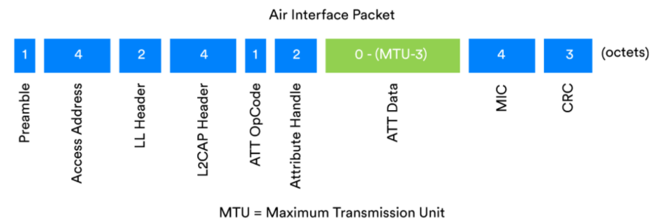
Figure 1: Encrypted Bluetooth LE packet with MIC field
Message Integrity Code (MIC)
Bluetooth LE packets are encrypted. All encrypted packets contain a field called the Message Integrity Check (MIC). Actually, MIC is a Message Authentication Code, but since the acronym MAC has other uses in the field of communications, in the Bluetooth specification, MIC is used.
The MIC itself is not a reliability feature. It is a security feature whose purpose is to be able to detect intentional attempts to tamper with the contents of a packet. However, since part of our informal definition of reliability is that the data transmitted should be the data received, and we acknowledge that changes may be accidental or intentional, we include it here for completeness.
After all, insecure communication cannot be considered reliable.
Spread Spectrum
Bluetooth technology uses the 2.4GHz ISM radio band. The 2.4 GHz ISM does not define a single frequency, but rather a frequency range, which in this case starts at 2400 MHz and ends at 2483.5 MHz. When used with Bluetooth LE, this frequency range is divided into 40 channels, each 2 MHz wide. Bluetooth BR/EDR divides it into 80 channels of 1 MHz width.
Each channel is numbered starting with channel zero. Channel zero has a center frequency of 2402 MHz, with a 1 MHz gap between the lowest frequency defining channel zero and the beginning of the ISM 2.4 GHz band. Channel 39 has a center frequency of 2480 MHz, with a 2.5 MHz gap between it and the end of the ISM 2.4 GHz band.
The following figure depicts the division of the ISM band into radio channels used by Bluetooth LE. Note that the channel numbers always increase in consecutive order from 0 to 39, and the channel indices are assigned to the ISM channel sets in a slightly different manner.

Figure 1. Bluetooth LE channels in the ISM 2.4 GHz band.
Bluetooth data communications use multiple radio channels, which makes Bluetooth communications highly reliable in busy radio environments where collisions and interference may occur.
Using multiple frequencies in this way is called spread spectrum, and the details of how it is used vary in different situations.
Solving coexistence and collocation issues
The use of the same radio band by many different radio technologies at the same time creates potential challenges. One technology may interfere with the transmissions of another technology, and these issues are collectively known as coexistence issues. Bluetooth technology, Wi-Fi, cordless DECT phones, and even microwave ovens all operate in the 2.4 GHz ISM band, so there may be coexistence issues between these technologies and device types.
The coexistence problem is mainly solved in Bluetooth by using spread spectrum technology. By using spread spectrum technology in Bluetooth in a specific way in this case, a higher reliability can be achieved when connecting two devices.
Collocation is a term used to describe the presence of multiple radios within the same device, each supporting a different communication technology or set of technologies. There is a certain range of interference between different radios within a device. Long Term Evolution (LTE) radios used in 4G mobile phone systems can operate in a frequency band adjacent to the 2.4 GHz ISM band, which raises potential issues such as preventing one radio from receiving while another is transmitting. Most collocation issues are outside the scope of the Bluetooth Core Specification itself, but recommendations are provided to implementers. Mitigations include the use of filters to reduce interference between radios and radio time slot scheduling considerations that implementers are advised to accommodate.
Radio slot scheduling is a complex issue that is concerned with determining when a radio is available and unavailable. Some aspects of scheduling fall within the scope of the Bluetooth Core Specification. Issues related to collocation with other radios and other considerations and constraints, such as those that may be imposed by the operating system, do not arise. However, a feature called the Slot Availability Mask (SAM) is defined that enables two Bluetooth devices to provide each other with information about which slots are available for use, and by taking this information into account in determining the scheduling used by each device, slots can be optimized to avoid using slots that may interfere with the configuration.
LE Coded PHY
Bluetooth LE provides three different ways to use the radio. These three choices are part of the physical layer, and each is referred to by the abbreviation PHY. The three PHYs defined are:
LE 1M – 1 Msym/s symbol rate
LE 2M – 2 Msym/s symbol rate
LE Coding – 1 Msym/s symbol rate with forward error correction (FEC)
LE Coded PHY increases receiver sensitivity so that a BER of 0.1% is not encountered until the distance between the receiver and transmitter is greater compared to LE 1M PHY. LE Coding is used with a parameter named S set to either 2 or 8. When S = 2, LE Coding approximately doubles the range at which communications can be reliable. When S = 8, the range is approximately quadrupled.
LE Coded PHY enables reliable communications at longer ranges without increasing transmit power by including extra data in each packet, allowing errors to be detected and corrected using a mathematical technique called forward error correction. The increase in range comes with a reduction in data rate, however, with S = 2 yielding 500 Kb/s and S = 8 yielding 125 Kb/s.
The main purpose of LE Coded PHY is to increase range, but this is achieved by reducing the bit error rate at lower signal strengths, making communications reliable enough at longer ranges.
Previous article:Four Myths About Ultra-Wideband (UWB) Technology
Next article:Laird Connectivity Wireless IoT Gateway Now Available at Mouser
- Popular Resources
- Popular amplifiers
- e-Network Community and NXP launch Smart Space Building Automation Challenge
- The Internet of Things helps electric vehicle charging facilities move into the future
- Nordic Semiconductor Launches nRF54L15, nRF54L10 and nRF54L05 Next Generation Wireless SoCs
- Face detection based on camera capture video in OPENCV - Mir NXP i.MX93 development board
- The UK tests drones equipped with nervous systems: no need to frequently land for inspection
- The power of ultra-wideband: reshaping the automotive, mobile and industrial IoT experience
- STMicroelectronics launches highly adaptable and easy-to-connect dual-radio IoT module for metering and asset tracking applications
- This year, the number of IoT connections in my country is expected to exceed 3 billion
- Infineon Technologies SECORA™ Pay Bio Enhances Convenience and Trust in Contactless Biometric Payments
- LED chemical incompatibility test to see which chemicals LEDs can be used with
- Application of ARM9 hardware coprocessor on WinCE embedded motherboard
- What are the key points for selecting rotor flowmeter?
- LM317 high power charger circuit
- A brief analysis of Embest's application and development of embedded medical devices
- Single-phase RC protection circuit
- stm32 PVD programmable voltage monitor
- Introduction and measurement of edge trigger and level trigger of 51 single chip microcomputer
- Improved design of Linux system software shell protection technology
- What to do if the ABB robot protection device stops
- Sn-doped CuO nanostructure-based ethanol gas sensor for real-time drunk driving detection in vehicles
- Design considerations for automotive battery wiring harness
- Do you know all the various motors commonly used in automotive electronics?
- What are the functions of the Internet of Vehicles? What are the uses and benefits of the Internet of Vehicles?
- Power Inverter - A critical safety system for electric vehicles
- Analysis of the information security mechanism of AUTOSAR, the automotive embedded software framework
- Brief Analysis of Automotive Ethernet Test Content and Test Methods
- How haptic technology can enhance driving safety
- Let’s talk about the “Three Musketeers” of radar in autonomous driving
- Why software-defined vehicles transform cars from tools into living spaces
- Anlu SparkRoad Development Board Review (7) MCU Soft Core IP Trial
- A DSP debugging and direct code generation method based on Matlab
- [Technical Tips] Power Supply PCB Design Skills and Case Analysis
- FPGA_100 Days Journey_VGA Design.pdf
- MakeCode graphical programming supports USB HID function
- EEWORLD University-How to improve the performance and reliability of motor drive and inverter applications? Introducing two simple and efficient methods
- The latest weekly evaluation intelligence, EE Evaluation Intelligence Bureau reports for you
- Pure hardware AC constant resistance load and INA related issues
- [FS-IR02 + D1CS-D54] - 1: Assembly (unique line color + unique labeling)
- [TI recommended course] #TI mid-power audio amplifier development software PurePath Console 3 detailed explanation#

 OP37GP


 京公网安备 11010802033920号