Two unique tube preamplifiers
Source: InternetPublisher:zht24 Keywords: Power amplifier circuit Updated: 2024/11/06
Two unique tube preamplifiers
Audiophiles all have their favorite pure power amplifier, whether it is a tube amplifier, a solid state amplifier, a homemade gun, or a foreign cannon. Different amplifiers have their own inherent characteristics. Based on the national conditions, most of the audiophiles in my country are working class, and there are very few people who can truly enjoy the wonderful sound of tube amplifiers.
This article introduces two tube preamplifiers with their own characteristics. They can be connected to various post-amplifiers to obtain the charming sound of tube amplifiers. Especially when used with the pure Class A post-amplifier launched by our company, the effect is more obvious and easy to "listen".
DS-9908 Tube Preamplifier

The principle is shown in Figure 1. At first glance, the circuit looks familiar. It is quite similar to the Marantz-7 tube preamplifier, but it is not. First, let's briefly analyze the circuit principle, and the differences are not difficult to find. The audio signal is input from the V1 grid, output from the plate, amplified and inverted; then coupled to the V2 grid through C2, further amplified and inverted again by V2, and an audio signal with the same phase as the amplifier input signal is output from the V2 plate; buffered by R9, it is sent to V3 for current amplification, and after reducing the impedance, it is coupled by C3 and output from WI. V3 and V2 are connected to form a direct-coupled cathode follower. The gate bias of V3 is obtained from the V2 plate, eliminating the inter-electrode coupling capacitor required for the self-biased cathode follower, which is conducive to the smooth passage of low-frequency signals. Thus, the frequency band is widened and the sound field is opened. The feedback signal is taken out from the V2 plate and fed into the V1 cathode through C10 and R5. C10 and R5 are fed into the V1 cathode. C10, R5, R2, and C1 together form a negative feedback network. Changing the values of R5, R2, and C1 can produce different listening effects (readers can change the values of R5, R2, and C1 to achieve the effect they are satisfied with). Compared with Marantz-7, the difference lies in the coupling and feedback method between V2 and V3. V3 of Marantz-7 adopts a self-biased working method, and the connection between it and V2 uses two capacitors in series to take the feedback signal from the series connection point. This is not an ordinary coupling, it is clearly a high-pass filter. Through practice, if you make it according to the Marantz-7 circuit published in some articles and magazines, you may not be able to achieve the expected effect, and its playback effect may not be satisfactory. However, this is not the case with the DS-9908 tube preamplifier. This preamplifier is slightly modified from the M7 circuit and uses DS-9908 to directly connect to the pure post-stage power amplifier. The music played has a relatively flat frequency band, the low frequency is magnificent, touching and free, the mid-range is bright, sweet and magnetic, and the high frequency is delicate and pleasant, and every detail is clear. The playback effect is quite unique.
DS-9908 SRPP tube preamplifier
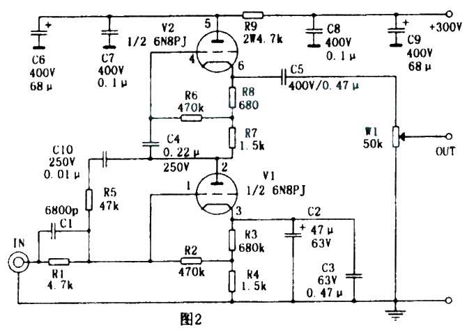
The schematic diagram of the SRPP tube preamplifier is shown in Figure 2. This is an improved SRPP circuit, which has been introduced in many audio publications and seems to have nothing special. This preamplifier uses AC voltage negative feedback technology that is not used in general SRPP circuits, making the circuit's signal amplification of each frequency band tend to be flat, and at the same time can effectively improve distortion. After the introduction of negative feedback, the low frequency that originally lacked strength is strengthened, and the sound field is also extended in depth. The working principle is briefly described as follows: From the perspective of the amplification process of AC signals, the SRPP circuit is actually what people often call a parallel push-pull amplifier. However, from the perspective of the DC working principle, it is two triodes connected in series in the power supply circuit. The gate of each triode adopts a self-supplied bias mode, and V2 rides on V1, so this circuit was once nicknamed "riding circuit" by audiophiles. The signal is sent to the gate of V1 by R1 and C1. After V1 is amplified, its screen outputs a signal with a phase opposite to the input signal, and then coupled to the gate of V2 through C4 for current amplification and impedance transformation, and then output from the cathode of V2 through C5 and W1. The negative feedback signal is taken out from the V1 screen and forms a negative feedback network through C10. By changing the values of C10, C1, and R1, different timbres can be obtained. The music played by this pre-amplifier is very humane, the low frequency is loose but not scattered and full of elasticity, the mid-frequency image is clear, the human voice is full of breath, and the treble is clear and accurate.
Both of these tube preamplifiers can directly drive 32Ω stereo headphones. When used to drive headphones, W1 must be moved to the input end. They use the same power supply, as shown in Figure 3. The principle is analyzed by the reader (the playback effect is different when the screen voltage of this preamplifier is different. Through practice, the playback effect is better when the screen voltage is about DC450V). The tube filaments are powered by AC 6.3V. When listening to the sound with 3212 headphones, the AC sound can be ignored when the volume is turned up to the maximum; when connected to the power amplifier, the volume is turned up, and the ear is 20em away from the speaker, the AC sound is not heard. The signal-to-noise ratio is above 90dB. When making, except for the resistors with power indicated, gold film resistors above 1/2W are preferred; ruby is suitable for electrolytic capacitors, which are voltage-resistant and have sufficient capacity; RIFA or WIMA MKP are preferred for non-polar capacitors; and J-grade or above can be selected for tubes.
- TDA2009A power amplifier circuit
- Field effect tube amplifier circuit with beautiful sound
- Single-ended Class A amplifier using gallstone composite tube design
- The production of 6P14 small tube amplifier
- 6AS7 tube amplifier
- Typical applications of optocouplers in audio amplifier circuits
- Auxiliary audio power amplifier circuit using LM4730/LM4731
- Single power supply audio power amplifier circuit composed of LM3875
- Horseshoe gallbladder preamplifier circuit
- Active power amplifier circuit composed of TDA2003
- DV (CL) type power amplifier circuit
- AP500 and its application circuit (d)
- Simple 100W power amplifier circuit
- 30W power amplifier circuit
- Field effect transistor OCL power amplifier circuit
- Two-stage difference amplifier OCL amplifier
- 50WOTL power amplifier circuit
- Pure DC FET power amplifier circuit 03
- Feiyue 12D3 black and white TV audio OTL power amplifier circuit
- Bridge power amplifier circuit for DC motor speed regulation


 京公网安备 11010802033920号