The easy production of several top-quality tube preamplifiers
Source: InternetPublisher:念慈菴 Keywords: Tube preamplifier circuit Updated: 2024/11/15
In the past few years, tube amps have been gradually recognized and accepted by people, and a wave of tube amp production has been set off in the audiophile circle. Among tube amps, the tube preamplifier has a relatively high production success rate because of its simple circuit and easy debugging. Since most audiophiles already have a transistor post-stage with good performance, a top-quality tube preamplifier can help you quickly enter the audiophile realm. The combination of "tubes in front and transistors in the back" may be more suitable for the tastes of most audiophiles. Here are several top-quality tube preamplifier circuits for audiophiles' reference. The following circuits are all dual-channel designs, only the main circuit of one channel is given, and the other channel is omitted.
1. Matellus preamplifier
The schematic diagram is shown below. This circuit imitates the British Magnetron "Reference" tube preamplifier. Magnetron tube preamplifier is famous for its outstanding design concept and pure and transparent sound quality. Its circuit is the most cost-effective among tube preamplifiers and is also the easiest to assemble. It uses 12AX7 and 12AT7 as two-stage amplifiers, with the characteristics of large output current, average full-frequency performance, high analytical power, and strong sound quality.
Audiophiles can also use the parallel tube method to tinker with this circuit. In this case, the left and right channels are each amplified by a 12AX7 and a 12AT7 (with a slight adjustment of the peripheral resistance). This will result in a higher channel separation and a more beautiful tone.

2. Improved Marantz 7-tube preamplifier
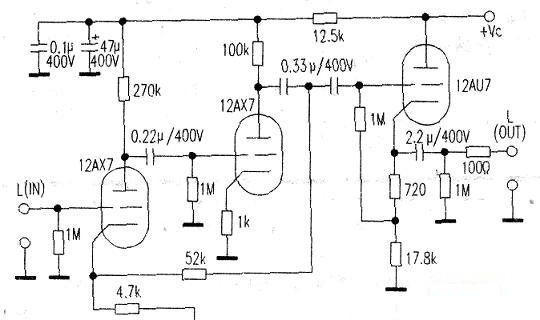
The principle is shown in the figure below. This circuit uses 12AX7 for two-stage amplification, followed by 12AU7 cathode follower as signal buffer. As we all know, the Malan Tu7 tube preamplifier is famous for its sweet mid-range.
But its analytical power and high and low frequency extension are not good. In view of the shortcomings of the traditional Marantz ±7 tube preamplifier, some adjustments have been made to the selection of coupling capacitor capacity and negative feedback loop. The improved Marantz tube preamplifier has a certain extension and sense of strength in high and low frequency reproduction, but the mid-frequency is better.
This tube preamplifier is most suitable for listening to vocals and string instruments.
 .
.
3. Wada Shigeshi gallbladder pre-stage
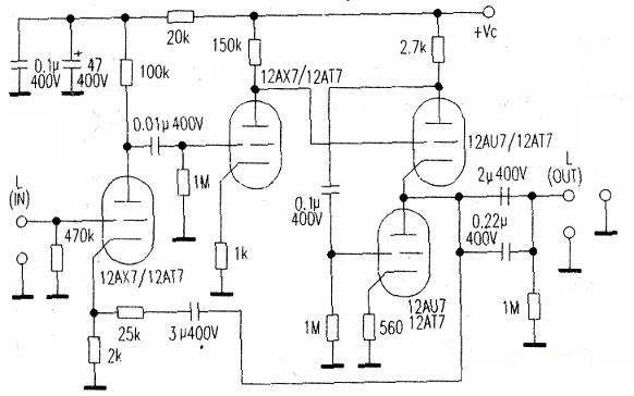
The schematic diagram is shown below. In view of some shortcomings of the traditional Marantz 7 circuit, Japanese Wada Shigeru improved the Marantz ±7 circuit. The improved circuit is called Wada Shigeru's circuit. Its main feature is to replace the cathode follower of the Marantz 7 circuit with the SRPP circuit. Since the SRPP output stage does not have any voltage amplification function, it is only used as a buffer stage. Compared with ordinary cathode followers, its load driving capacity is stronger. In terms of timbre, it maintains the sweet and mellow characteristics of the Marantz 7 circuit. Its analytical power and high and low frequency response are better than Marantz 7, and the signal-to-noise ratio is relatively high. The electronic tubes used in this circuit can also be replaced with 12AT7.

4.JADIS tube preamplifier
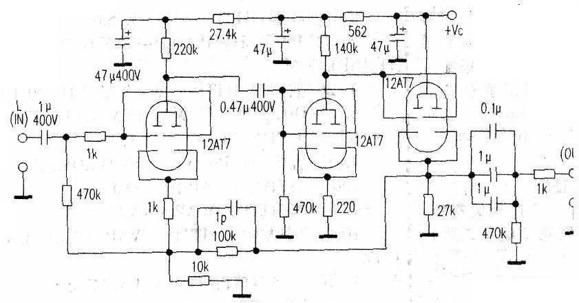
The schematic diagram is shown below. This circuit is taken from the classic circuit of the French "JADIS JP2000" flagship preamplifier. It uses 12AT7 for two-stage voltage amplification and 12AT7 for cathode output. This allows the impedance of the front and rear stages to be well matched and improves the load capacity. In order to obtain a larger output current and lower output impedance, this circuit uses dual triodes in parallel, which is also one of its characteristics. Its sound quality is mellow and transparent, with a stronger musical flavor than Marantz 7, and its highs and low frequencies are also significantly better than Marantz 7, making it most suitable for enjoying classical music.

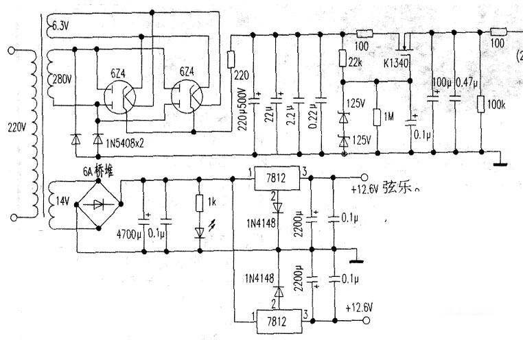
The figure below is a simple and easy-to-make tube amplifier voltage regulator with outstanding performance. This circuit combines the characteristics of electron tubes and transistors, taking advantage of their strengths and making up for their weaknesses, while also reducing the process requirements for the power transformer. The high voltage is stabilized by Hitachi field effect tubes, and the filament is powered by DC +12. ", which can further reduce the noise of the whole machine. The above tube pre-stage can be used with this power board except for the improved Marantz 7 (this board is a large board with tube rectification, tube voltage regulation, main board, and power supply integrated with double-sided gold plating).
For tube amplifier production, some audiophiles particularly advocate the scaffolding welding method. However, for beginners, the success rate is not high, the noise is difficult to deal with, and it is purely handmade, the output is not large, and it is not suitable for mass production. The author believes that if tube amplifiers want to be popularized, they should be combined with circuit board assembly production. The circuit board used by the old pen is made by a professional circuit board manufacturer. The main board is a thickened double-sided polycarbonate gold-plated glass fiber board, and the power board is a single-sided glass fiber board, which is convenient for machine adjustment. The printing on the board is clear. As long as you have a basic understanding of radio, even if you have never assembled a tube amplifier, you can assemble it according to the values marked on the printed board to ensure that you will assemble it successfully once. The signal-to-noise ratio of the installed whole machine reaches or exceeds that of similar products with scaffolding welding. In the dead of night, turn the volume to the maximum, and only hear a slight background thermal noise of the tube when your ear is close to the speaker.
As the saying goes, "A good horse deserves a golden saddle". In the production of tube amplifiers, the selection of components is also crucial. To ensure quality, it is recommended to use new components. The author uses the kit provided by the manufacturer. The electronic camp is a domestic export product, and the resistors are 2W and 3W American resistors, such as DALE resistors, AB carbon resistors, etc.
For capacitors below 4.7μF/400V, the French Soulen SMKP capacitors with a strong musical flavor are used, and for electrolytics, brands such as ELNA, ERO, SAMWHA, and Rubycon are used. For transformers, there are two specifications, 100WE and R, made of grade A materials, for audiophiles to choose from. For related components such as sound source selection and volume control, there are also many options to choose from, such as relay sound source switching, manual volume control board, top volume remote control board (relay switching photoresistors of different resistance values), gold-plated input and output terminals, luxury chassis, etc. The whole machine assembled in this way is not inferior to some high-quality machines in terms of sound quality or appearance, changing the situation where "homemade" products cannot be accepted by the public.
During assembly, refer to the schematic diagram and use high-quality solder wire with a high silver content to solder all components to the circuit board (including the tube sockets), install the mainboard and power board, and use a multimeter to measure the power board output DC high voltage, which should be around +250V, and the filament voltage should be +12.6V. If the voltage is normal, check that the mainboard components are assembled correctly, then you can install the mainboard tubes, connect the power cord and input and output sockets, and test the sound.
If the sound test is normal, you can install all the components into the tube preamplifier chassis. After the whole machine is assembled, you can slowly enjoy the intoxicating sound of the audiophile tube amplifier!

- Share a mini piano circuit
- Tutorial on making a MIDI arpeggio synthesizer
- Using TDA2822 to do direct coupler output experiment
- Using 6P15 to create an ultra-linear push-pull amplifier
- Make cheap speakers using waste circuit boards (TDA1013)
- Electronic bird repeller for crops
- Audio power amplifier circuit powered by a single power supply using LM1875
- Dual power supply audio power amplifier circuit composed of LM3875
- LM4820-6 audio power amplifier circuit
- Active power amplifier circuit composed of TDA2003
- LA4461N audio IC circuit
- TDA2030 audio power amplifier circuit diagram
- Voice controlled bird circuit
- Transistor Audio Mixer Circuit Diagram
- 2-tube FM microphone with 3V power supply
- Simulating bird call circuit schematic diagram
- Several good field effect transistor power amplifier circuit diagrams
- Squelch Tuned Audio Switching/Mixing Circuit Diagram
- transistor audio mixer
- High quality melody circuit


 京公网安备 11010802033920号