Ceramic filter structure/working principle/characteristics/application
Source: InternetPublisher:念慈菴 Keywords: Filters Updated: 2024/12/31
1. Working principle of ceramic filter
The ceramic filter consists of a porous body in which several main flow paths of the fluid to be purified penetrate from one end face to the other end face, and the filter membrane is installed on the inner wall surface of the main flow path. (1) The fluid to be purified flows into the main flow path through the opening on the end face, then passes through the filter membrane and the interior of the porous body to be purified, and is taken out from the outer peripheral surface of the porous body as a purified fluid. (2) The fluid to be purified flows into it through the outer peripheral surface of the porous body, then passes through the interior of the porous body and the filter membrane to be purified, and is taken out from the opening on the end face of the main flow path as a purified liquid.
2. Main features of ceramic filters
1. It has excellent corrosion resistance to all corrosive liquids except hydrofluoric acid and concentrated alkali;
2. Good heat resistance, no thermal deformation, softening or oxidation. It can still be used at higher temperatures;
3. The gas is evenly distributed and can form an aperture of 0.1~600mm as needed;
4. High rigidity, no shape change and pore deformation under the action of fluid pressure;
5. In the case of precision filtration (as a special case), in order to prevent contamination of the liquid, a trace amount of exudate is not allowed. When using a ceramic filter, there is usually no exudate and it also meets the requirements under the Food Sanitation Law. Therefore, it can be adopted in the poultry industry.
6. Solids collected by the ceramic filter accumulate outside the filter layer or inside the filter layer, blocking the pores of the filter, so that the filtering capacity will decrease. This blockage state can take many forms, such as solids collected on the surface; solids entering the inner layer of the filter; solids accumulate on the surface to form a rough surface (such as the filter layer). In these cases, although the filtering capacity gradually decreases, the degree of decline is different.
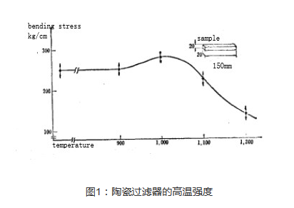
7. Although ceramic filters can be used in high-temperature areas that other porous bodies cannot reach, they are best used in high-temperature areas below 1000°C; filtering combustion exhaust gases, molten metals and blowing air into the nozzles of high-temperature furnaces at 1000°C.

8. For clean fluids, the amount of fluid permeation through the ceramic filter layer is proportional to the area and pressure difference, and inversely proportional to the plate thickness and viscosity coefficient. The filter (filter) layer is regarded as a collection of capillaries, and the fluid flow through the capillaries can be expressed by the following formula:
v=(π·d4·ΔP)/(128η·l)=(π·d4·ΔP)/(128α·h·L)
In addition, the relationship between the air binding rate and ε; and the number of capillaries per unit area N and the diameter of the capillary d can be expressed by the following formula:
ε=(π/4)d2·N
Therefore, the penetration V can be expressed by the following formula:
V=N·v=(d2·e·ΔP)/(32α·n·L)
In the formula,
V—permeation volume per unit area per unit time (cm3/cm2·sec); Δ pressure difference (dyne/cm2);
L – thickness of the filter (filter) layer (cm);
Capillary diameter (cm);
l—capillary length (cm);
α——curvature (1~3).
In other words, the amount of fluid permeation through the ceramic filter layer is proportional to the porosity of the filter and the square of the capillary diameter. Increasing the amount of binder, expanding the particle size distribution range, etc. will reduce the porosity and ε; and the amount of liquid permeation. Therefore, the amount of binder and the particle size distribution should be used as the manufacturing conditions of the filter.
3. Structure and materials of ceramic filters
The research on ceramic filtration mainly focuses on two aspects: one is the material of the ceramic filter, including its manufacturing process and performance; the other is the structure of the ceramic filter, including its shape, placement, filtration mechanism and filtration effect.
The selection of filter materials should be based on the type of inclusions to be removed by the filter, and the creep resistance and thermal vibration resistance of the material should also be considered. A large number of experiments have shown that the material, porosity and inner surface roughness of the ceramic filter will affect the filtering effect.
The structure of ceramic filters is determined by their materials. According to the different materials, ceramic filters can be divided into two categories: ceramic foam filters and particle ceramic filters.
(1) Foam ceramic filter
The open pore volume of ceramic foam filters is 75% to 90%, and they are usually classified according to the number of pores per inch (ppi). For example, the pore size of a 10 ppi ceramic foam filter is 1778 μm; the pore size of a 30 ppi ceramic foam filter is 711 μm. The thickness of the ceramic foam filter is generally 25 mm. In the pouring system, there are vertical installation and horizontal installation. The structure is designed according to the specific purpose.
Materials used for ceramic foam filters include NCL-mullite, ZrO2, Zr-SiO4, Al2O3, etc. Al2O3 foam ceramics are used, which are not easy to break during operation and have good resistance to thermal vibration and cracking. They have strong resistance to creep deformation under the flow of high-temperature molten metal at 1700°C. Due to the high porosity (75% to 90%) and thin pore walls of the open pores, the foam ceramic filter does not need to be preheated before contacting with the molten metal.
(2) Ceramic particulate filter
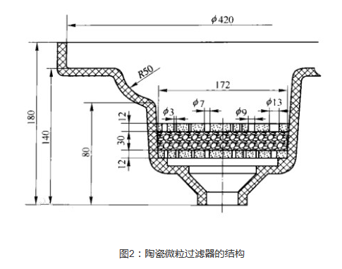
The structure of the ceramic particulate filter is a support plate with upper and lower holes, with a particle filler in the middle, and a layer of active adsorbent material coated on the particle filler, as shown in the figure below. The thickness of the support plate is generally 12 mm, and the pore size is 4.5 to 13 mm. The ceramic particulate filter replaces MgO or Al2O3 as a filler and uses an active adsorbent depending on the type of inclusions to be filtered.

CaO refractory is a good filler for ceramic particulate filters. It can not only utilize the principle of physical adsorption, but also remove inclusions through chemical reaction. However, there are two reasons that limit its widespread use. First, it requires extremely high sintering temperatures (above 1800°C;C) to obtain the necessary density and mechanical strength. Second, it is easy to add water at normal temperature and atmosphere.
The advantages of CaO refractory materials are high refractoriness, high basicity, good molten steel filterability, and extremely abundant resources. The methods to improve the water resistance of CaO refractory materials for molten steel filtration are as follows:
(1) Vigorously improve the sintering degree of CaO refractory materials, larger crystal size, and use ultra-high calcined or molten lime;
(2) Forming a protective film on the CaO surface;
(3) Dip-coating tar or organic resin film on the CaO char product as an intermediate transition measure;
(4) Add a small amount of chemical additives to CaO to reduce the sintering temperature of CaO.
4. Application of Ceramic Particulate Filters
At present, ceramic filters are increasingly used in many industrial fields such as catalytic precious metal recovery, fluidized bed combustion, calcination, organic waste gasification power generation, building materials, chemicals, various industrial kilns and other industrial processes, high-temperature flue gas purification. The application of high-temperature flue gas purification also appears in smelting, material production, glass manufacturing and other processes that are often carried out under conditions close to atmospheric pressure.
The most prominent application of ceramic filters is the purification of smoke in the field of coal-fired power generation. As the global demand for electricity continues to increase, coal is the main source of solving the power problem. Regarding the non-renewable nature of such fossil fuels, it is necessary to maximize the efficiency of power generation and reduce air pollution in countries around the world, especially in China, a major coal-burning country. The improvement of power generation efficiency can be achieved through circulating fluidized bed (CFBC) power generation and coal gasification (IGCC) power generation, as well as their combination. The power generation process of coal gasification is different from that of traditional steam engines. After the coal is heated and vaporized, the coal gas needs to be purified before entering the gas generator (gas engine). That is, any dust or other impurities must be removed. Most power plants limit the allowable dust concentration entering the gas turbine to less than 5 mg/m3.
Theoretically, it is better to be less than 1 mg/m3. The working temperature of the dust removal system is often 350~1000°C and the pressure is 1~2.5SPa. Therefore, to achieve such a high purification effect under such high temperature and pressure, ceramic filters must be the first choice.
- Capacitance detection circuit configuration, how to deal with low frequency and high frequency noise?
- What are the classifications of filters?
- What is the difference between CPLD and FPGA?
- What is power factor and three ways to improve it
- Working principle/advantages/disadvantages/size of optical fiber
- Share an interesting LED decoration project
- LED Night Light
- LED Bicycle Lights
- Circuit diagram of an example of differential and integral circuits
- Rectangular Pulse Frequency Doubler
- 20Hz High Pass Turntable Noise Filter
- 555 square wave oscillation circuit
- 555 photo exposure timer circuit diagram
- Introducing the CD4013 washing machine timer circuit diagram
- Simple level conversion circuit diagram
- 555 electronic guide speaker circuit diagram for blind people
- Circuit diagram of disconnection alarm composed of 555
- Analog circuit corrector circuit diagram
- color discrimination circuit
- Color sensor amplification circuit


 京公网安备 11010802033920号