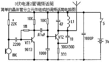
2-tube FM microphone with 3V power supply
Source: InternetPublisher:公子李 Keywords: FM microphone audio circuit frequency modulation Updated: 2020/01/03
One of the two transistors is used for audio amplification, and the other is a high-frequency oscillation tube and frequency modulation tube. The first-level audio amplifier is composed of VT1 (9013), which amplifies the audio signal output by the electret microphone and couples it to the base of the high-frequency oscillation tube VT2 through the capacitor C2. The frequency of the high-frequency oscillation circuit is adjusted to the FM broadcast band of 88-108MHz, which is convenient for debugging with FM radio. This frequency is adjusted by the LC resonant circuit L1 and C4, and the audio signal sent from VT1 will frequency modulate this frequency. When the audio signal is coupled to the base of VT2 via C2, the oscillator frequency will continuously change with the audio signal to generate the required FM frequency modulation signal, which is transmitted through the antenna. FM microphone circuit diagram composed of simple transistors and other discrete components:

The microphone MIC uses a high-sensitivity electret microphone, and the outer casing is connected to the negative pole. VT1 can use 9013 or 9014 with larger magnification, and VT2 can use high-frequency tubes such as 3DG130 and 9018. The L1 oscillation coil is made of Φ0.71 enameled wire densely wound with 4 turns on a 3mm round rod. The antenna uses a 1m soft wire, and the transmission distance can reach about 200m. The normal operating current of the circuit is about 5mA.
- Preamplifier circuit made of composite screen triode electron tube 6C5P
- Using TDA2822 to do direct coupler output experiment
- Sugon New Tube 2A3C Single-ended Tube Amplifier
- Making a Simple Tube FM Radio
- Design of a tube amplifier that uses the mains electricity to directly provide screen working power
- Installing a tube preamplifier in the power amplifier
- Auxiliary audio power amplifier circuit using LM4732
- LM4820-6 audio power amplifier circuit
- Horseshoe gallbladder preamplifier circuit
- Stereo amplifier circuit with Av=200 (gain) composed of LM1877
- LA4461N audio IC circuit
- TDA2030 audio power amplifier circuit diagram
- Simulating bird call circuit schematic diagram
- transistor audio mixer
- Robot sound generator
- Circuit diagram of a tube 40W amplifier
- TDA2030 audio power amplifier circuit diagram
- Music sound control level indicator circuit diagram
- Practical sound level monitor circuit diagram
- Car steering and reversing audio circuit


 京公网安备 11010802033920号