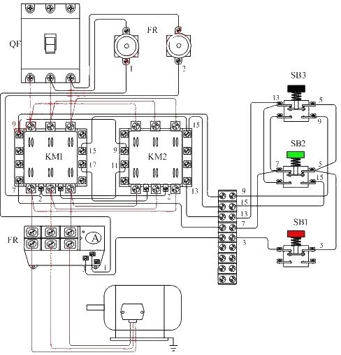
Motor forward and reverse control wiring diagram (2)
Source: InternetPublisher:黄土马家 Keywords: Wiring diagram motor forward and reverse control BSP Updated: 2020/03/07
This circuit is a motor reversible operation control circuit diagram based on the motor forward and reverse control wiring diagram (1). This circuit shares the AC contactor wiring diagram to check whether the main circuit wiring is correct. In order to ensure that the phase sequence of the motor can be reliably changed when the two contactors operate, the upper wiring of the contactor should be consistent during wiring. The lower port of the contactor is phase-modulated. Then, after checking that the wiring is correct, conduct a power test. To prevent accidents during the power test, the motor wiring should be disconnected first. As shown below.

- 5 Converter Topologies for Integrated Solar and Storage Systems
- Introduction and principle analysis of switching regulated power supply
- Energy-saving motorcycle rectifier regulator
- BA6104 five-digit LED level meter driver integrated circuit basic application circuit
- Use pulse width modulation to get a precise output voltage
- Principles and precautions of active discharge circuit
- How to use SBR to improve power conversion efficiency
- Using CW34603 to form a circuit to change the polarity of the output power supply
- Dual forward converter schematic diagram
- Integrated regulated power supply with continuously adjustable output voltage
- Rice mill circuit
- Farmland drainage automatic control circuit
- AC voltmeter
- Varactor Diode Frequency Modulator
- Simple AGC circuit in transistor radio
- Capacitive feedback oscillator circuit
- Voltage series negative feedback amplifier circuit
- Voltage controlled power supply second-order high-pass filter circuit
- Fault signal trip circuit
- Motorcycle flash light circuit


 京公网安备 11010802033920号