An automated model railroad layout project using a microcontroller
Source: InternetPublisher:司马缸砸光 Keywords: Microcontroller Motor Driver Updated: 2024/12/17
This article will describe a basic model train layout that includes a passing siding, with trains running and stopping in an automatic sequence.
Making model train layouts is a great hobby, and automating them makes it even better! Let's look at some of the advantages of automating it:
Low cost operation: The whole layout is controlled by an Arduino microcontroller, using L298N motor drivers, which cost almost nothing compared to conventional train control throttles and power packs.
Ideal for placement on a monitor: Since no human intervention is required to maintain control of the layout, you can use it to control trains and switches on a monitor where you cannot always be present.
Great for Microcontroller Hobbyists: If you are or want to get started with Arduino and programming, this is a great project to hone your skills.
So, without further ado, let’s get started!
Step 1: Watch the Project

Step 2: Get All Parts and Assemblies
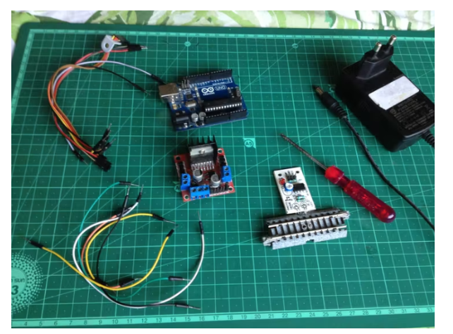
First, make sure you have all of the following:
An Arduino microcontroller board, UNO is preferred.
L298N dual H-bridge motor driver board.
6 male to male jumper wires.
7 male to female jumper wires.
A screwdriver.
A 12 volt DC power adapter.
Track segment with IR proximity sensor on the bottom (I used KatoS62 track)
Step 3: Upload the Program to the Arduino Board
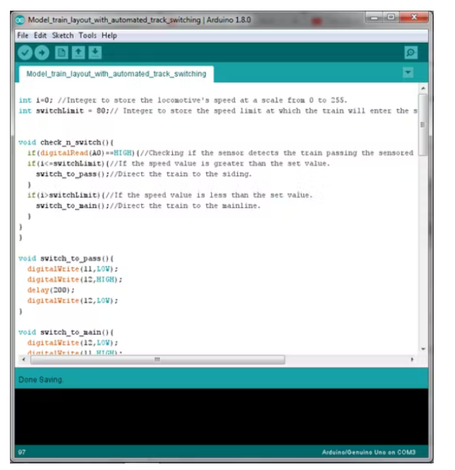
If you don't have Arduino IDE on your computer, please download it first. Then use this code:
inti=0;//Integertostorethelocomotive'sspeedatascalefrom0to255.
intswitchLimit=80;//Integertostorethespeedlimitatwhichthetrainwillenterthesiding.
void check_n_switch() {
if(digitalRead(A0)==HIGH){//Checkingifthesensordetectsthetrainpassingthesensoredtrack.
if(i《=switchLimit){//Ifthespeedvalueisgreaterthanthesetvalue.
switch_to_pass();//Directthetraintothesiding.
}
if(i》switchLimit){//Ifthespeedvalueislessthanthesetvalue.
switch_to_main();//Directthetraintothemainline.
}
}
}
void switch_to_pass() {
digitalWrite(11,LOW);
digitalWrite(12,HIGH);
delay(200);
digitalWrite(12,LOW);
}
void switch_to_main() {
digitalWrite(12,LOW);
digitalWrite(11,HIGH);
digitalWrite(11,HIGH);
delay(200);
digitalWrite(11,LOW);
}
void setup() {
pinMode(A0, INPUT);
pinMode(9,OUTPUT);
pinMode(10,OUTPUT);
pinMode(11,OUTPUT);
pinMode(12,OUTPUT);
}
void loop() {
switch_to_pass();//Switchingturnoutstothesidingsincethetrainwillstartthejourneyfrothere.
for(i=0;i《=40;i++){//Increasingthespeedofthelocmotiveto40,atthisspeedthelightsturnonbutthetrainremainsatrest.
analogWrite(9,i);
delay(10);
}
delay(1000);
for(i=40;i《=90;i++){//Increasingthespeedofthelocomotiveto90
analogWrite(9,i);
check_n_switch();
delay(500);
}
delay(4000);
for(i=90;i《=180;i++){//Increasingthespeedofthelocomotiveto180.
analogWrite(9,i);
check_n_switch();
delay(250);
}
delay(3000);
for(i=180;i!=90;i--){//Decreasingthespeedofthelocmotivebackto90.
analogWrite(9,i);
check_n_switch();
delay(500);
}
delay(2000);
while(digitalRead(A0)==LOW){//Waitforthetraintocrossthesensoredtrack.
}
switch_to_pass();//Switchtheturnoutstodirectthetraintothesiding.
delay(2000);//Waitforthetraintoenterthesiding.
for(i=90;i!=35;i--){//Reducethespeedofthetraingradually,bringingittoahalt.
analogWrite(9,i);
check_n_switch();
delay(500);
}
for (i=35;i!=0;i--) {
analogWrite(9,i);
check_n_switch();
delay(62);
}
delay(5000);//Waitfor5secondsbeforerepeatingthewholeprocessagain.
}
Step 4: Lay Track and Layout
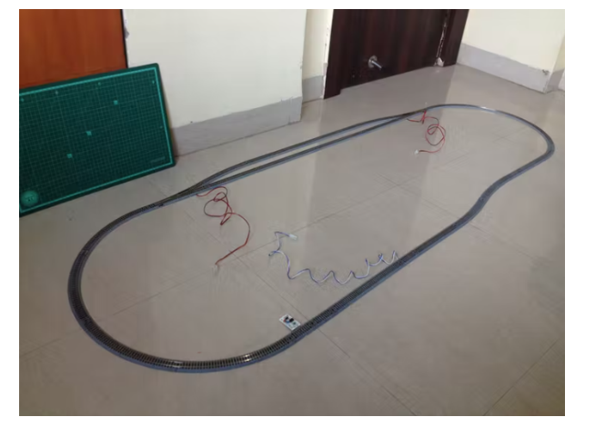
Make an oval loop with the siding going through as shown above. Make sure the distance between the sensor track and the first switch the train will go through after crossing the sensor track is greater than the length of the train so that no part of the train goes past the sensor track when it passes through the switch.
Step 5: Circuit Schematic
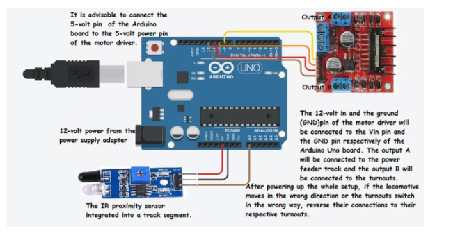
Before continuing, make sure you review the complete circuit schematic and all the details.
Step 6: Connect the Turnouts to the Outputs of the L298N Driver Board
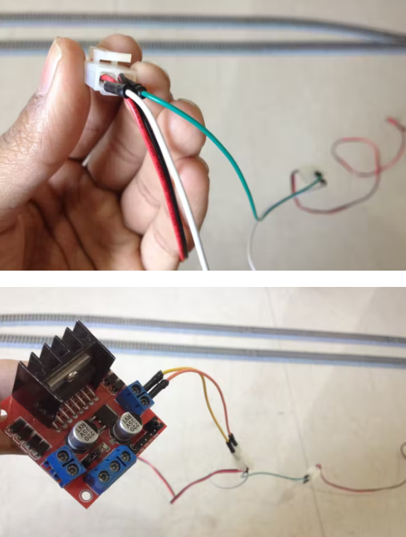
Connect the red and black wires of the two turnouts to each other to form a parallel connection. Then, connect the red wire to the out4 terminal of the motor driver board and the black wire to the out3 terminal of the motor driver board.
Step 7: Connect the Power Feed Rail to the Remaining Output of the L298N Driver Board
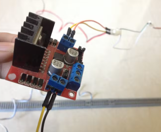
Connect the white wire of the power feeder to the out1 terminal of the motor driver board, and the blue wire to the out2 terminal of the motor driver board.
Step 8: Connect the L298N Driver Board to the Power Pins of the Arduino Board
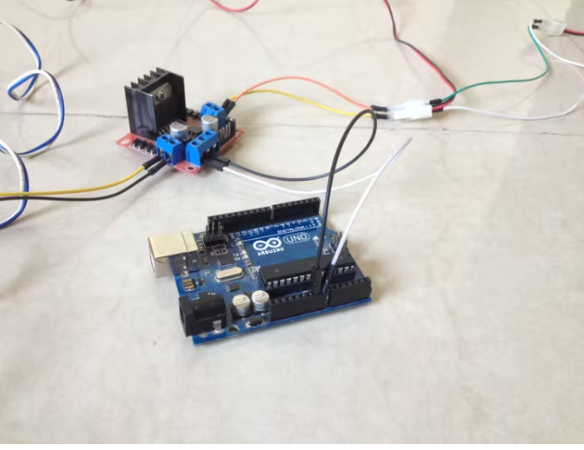
Connect the 12 volt pin to the VIN pin of the Arduino board, the GND pin to the GND pin of the Arduino board, and preferably the 5 volt pin of the motor driver to the 5 volt pin of the Arduino board.
Step 9: Connect the Sensor to the Arduino Board
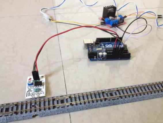
Connect the VCC pin of the sensor to the 5V pin of the Arduino board, the GND pin to the GND pin of the Arduino board and the OUT pin to the A0 pin of the Arduino board.
Step 10: Connect the Input Pins of the Motor Driver to the Arduino Board

Connect the digital pins of the Arduino board to the input pins of the motor driver board as follows:
D9 to IN1
D10 to IN2
D11 to IN3
D12 to IN4
Step 11: Put the Train on the Track
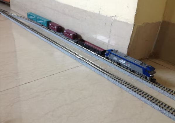
After checking all wiring connections, place the train on the siding.
Step 12: Startup Setup
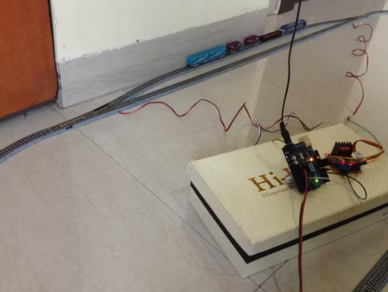
Start the setup and make sure the turnout switches to the siding, if not then simply reverse the connection of the turnout made to the motor drive. Also, make sure the train starts moving forward. If the train is running in the wrong direction then reverse the connection of the feeder track to the motor drive.
Step 13: Done!
At this point, the project is complete. You can modify the Arduino code to change the functionality of the layout, add more side panels, etc. It's all customizable!
- Design and selection of electric control valve system drive
- How to choose the right level of integration to meet motor design requirements?
- Controlling LEDs with Multithreading via Dual-Core Programming on Raspberry Pi using MicroPython
- How to Make a Simple Chicken Incubator
- How to make a wheeled self-balancing robot using ultrasonic sensors
- Introduction to the internal structure of the Delta winding motor
- One-way rotation circuit of motor controlled by contactor
- An experimental model of an infrared radio alarm
- Motorcycle anti-theft device circuit design
- Password type motorcycle anti-theft device
- USB communication circuit
- Rural fish farming control circuit
- Agricultural spraying and insecticide control circuit
- Photocell trigger control circuit
- Ringtone control circuit
- Traffic traffic light control circuit
- Table printing machine control circuit
- Digital current loop control circuit
- Micro DC motor steady speed control circuit a
- Voltage servo motor and control circuit


 京公网安备 11010802033920号