Controlling LEDs with Multithreading via Dual-Core Programming on Raspberry Pi using MicroPython
Source: InternetPublisher:王达业 Keywords: LEDs Micropython Updated: 2024/12/19
In this tutorial, we will use Micro Python to control two LEDs via multithreading with dual-core programming on a Raspberry Pi Pico .
So far, we have seen how to connect OLED, LCD, Servo, Ultrasonic Sensor and we have implemented I2C, ADC, Bluetooth communication with Raspberry Pi Pico . The RP2040 microcontroller pico board has dual cores. If you are not familiar with multithreaded execution, then think of your computer system. It can execute multiple programs at the same time which can be run by an operating system using multithreading. But we don't have any operating system on Raspberry Pi Pico to control the CPU cycles, it can only support one thread per core, in this case two.
Components required for dual-core programming on the Raspberry Pi Pico
You will need to make sure you have the following components to demonstrate dual core programming on the Pico board.
Raspberry Pi
LED x2
Resistor x2 (330 ohm)
Breadboard
Connect the wires
Servo Motor Circuit Diagram using Raspberry Pi Pico Board
The circuit diagram of the servo motor is as simple as this. I have connected two LEDs using two 330 ohm resistors with GPIO15 and GPIO16 respectively. The ground pin of the LED has been connected to the ground pin of the Pico board.

Multithreading on the Raspberry Pi Pico using dual-core programming
You need to clone our Raspberry Pi Pico Tutorials GitHub repository. Then open the "T9_DualCore_Prog ram_PIco" folder. In this folder, you can find the "code" folder. Open the "main.py" python file in the Thonny editor. Now, let's discuss the main.py file.
Imported from machine
Import u
First, we need to import the Pin() class from the machine.py library mentioned above. We have used the machine library several times in our previous tutorials and hopefully you are familiar with it by now. Then we need to import the "utime" library to use the internal clock of the pico. We are using the "_thread" library to use the threading functions made by the raspberry pi pico community.
led1 = Pin(16, machine.Pin.OUT)
led2 = Pin(15, machine.Pin.OUT)
sLock = _thread.alloca
In the above code, I initialize the two LEDs of GPIO15 and GPIO16 as OUPUT using the "Pin(16, machine.Pin.OUT)" and "Pin(15, machine.Pin.OUT)" functions. The "_thread.allocate_lock()" function can be used to provide a semaphore lock for two threads. If you want to know more about this function, you can refer to the documentation of the "_thread" library.
Define the core task():
    And true:
        sLock.
We will use the "CoreTask()" function in another kernel in a single thread. In the while loop inside the function, we use a semaphore lock to hold the thread until it is finished. I then turn led2 high for 1 second and then print the instructions on the output of Thonny. I then release the semaphore lock when the thread is finished. The "_thread.start_new_thread(CoreTask, ())" function will start the thread. This function takes the target function name as the first argument. In my case, it is "CoreTask" and it accepts arguments in the second argument. In my case, I don't have any arguments to pass.
And true:
    # We acquire the semaphore lock
    sLock.acquire()
    print("Entering the main thread")
    led1.toggle()
    utime.sleep(0.15)
    print("Led 1 starts switching.")
    print("Exit main thread")
    utime.sleep(1)
    # We release the semaphore lock
    sLock.release()
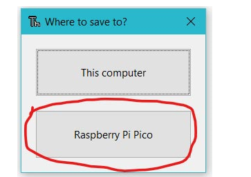
In the while loop above, we have similarly used another semaphore lock so that the main thread continues to run until it is finished. It will toggle led1 and then release the semaphore lock. Now, in Thonny IDE, open the "main.py" file. First, save the "main.py" file on your Pico board by pressing the "ctrl+shift+s" keys on your keyboard. Before saving the file, make sure your Pico board is connected to your laptop . After saving the code, a pop-up window will appear as shown in the figure below. You must first select the Raspberry Pi Pico and then name the file "main.py" and save it. This process enables you to run the program while the Pico is open.

When you upload and run the code on Pico board, you will see led1 connected to GPIO16 toggles with a delay of 1.15 seconds. But led2 connected to GPIO15 blinks with a delay of 2 seconds. You can refer to the video below for more details.
Code
Main File
Imported Machine
Importing utime
import_thread
led1 = machine.Pin(16, machine.Pin.OUT)
led2 = machine.Pin(15, machine.Pin.OUT)
sLock = _thread.allocate_lock()
Define the core task():
    And true:
        sLock.acquire()
        print("Enter the second thread")
        utime.sleep(1)
        led2.high()
        print("Led 2 is on")
        utime.sleep(2)
        led2.low()
        print("Led 2 is off")
        utime.sleep(1)
        print("Exit from the second thread")
        utime.sleep(1)
        sLock.release()
_thread.start_new_thread(CoreTask, ())
And true:
    # We acquire the semaphore lock
    sLock.acquire()
    print("Entering the main thread")
    led1.toggle()
    utime.sleep(0.15)
    print("Led 1 starts switching.")
    utime.sleep(1)
    print("Exit main thread")
    utime.sleep(1)
    # We release the semaphore lock
sLock.release() - Car ice warning circuit sharing
- Use your smartphone to turn on/off the power in your home
- How to Make a Hot Tub Smart and Remotely Operated with a Raspberry Pi
- What is a RADAX motor?
- Replace the GE LOGIQ a200 ultrasound measurement key with a self-made touch switch
- Motor automatic cycle control circuit
- Motorcycle anti-theft device circuit design
- Delay switch made with LM431
- Precious home appliance anti-theft alarm
- Car audio system anti-theft circuit
- Do you know about the YTSwitch-6 LED driver IC with high efficiency and extremely low standby power?
- MAX8631X driving white LED circuit diagram
- SG1524 driver LED circuit
- "clairvoyance" charger circuit diagram
- MEMS strobe driver circuit diagram
- Positive terminal buck/boost LED constant current drive circuit diagram
- Digital camera flash control circuit
- Household electric blanket power saving circuit
- Alkaline battery charger circuit diagram
- Eight-way light-touch electronic interlock switch circuit


 京公网安备 11010802033920号