Tutorial on making a handheld Geiger counter
Source: InternetPublisher:黄土马家 Keywords: Counter Handheld Instrument OLED Display Updated: 2024/12/24
This project measures radioactivity using a 3D printed housing with an OLED display and a lithium-ion battery.

The project started after I bought an off the shelf Geiger counter kit.
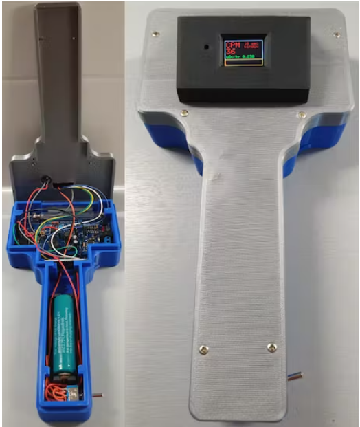
My whole idea was to put this kit in a 3D printed enclosure so that the complete Geiger counter kit could be handheld. The end result is shown below:
Step 1: System Design
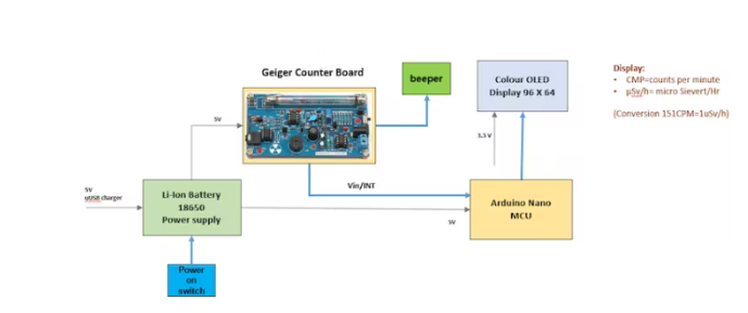
The design of a handheld Geiger counter is shown below:
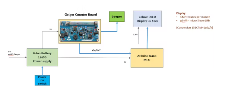
The Geiger counter is equipped with a 0.96-inch color OLED display that informs the user of the measured CPM (measurement of the detection rate of ionizing events per minute) and the dose equivalent (in µSv/hr) by a simple factor 151. The type of Geiger-Mueller (GM) tube used can be found in the literature.
In fact, the displayed CPM is the result of calculating the counts for one minute by measuring the counts per second (CPS) and storing these measurements in an array covering the past ten-second period. The total counts during the past 10 seconds are multiplied by 6 to obtain the CPM value.
The count over the past second is used to display the instantaneous number of measurements via a bar graph on the OLED display. This is useful in the case of high count rates, or when rapid changes in count rate occur when the handheld counter is moved over a radiation source.
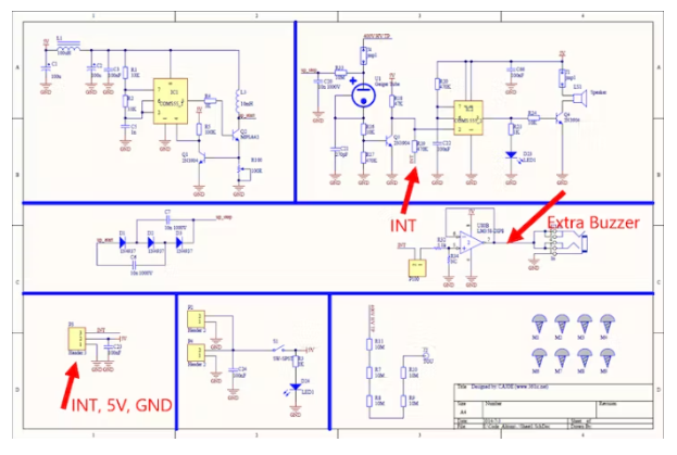
The Geiger Counter is powered by a 18650 type Li-Ion battery which can be recharged via a micro USB plug. The Arduino Nano USB port can also be used for software changes. An additional buzzer is connected to the Geiger Counter board to enhance the ionization sound in the GM tube.
All of the electronics for the Geiger counter are built into the 3D printed housing:
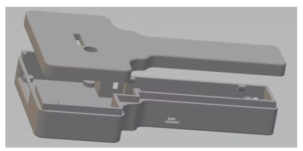
The OLED display is placed in a separate box on top of the Geiger counter:
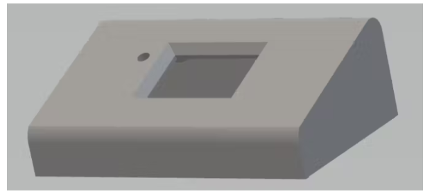
Fully assembled version:
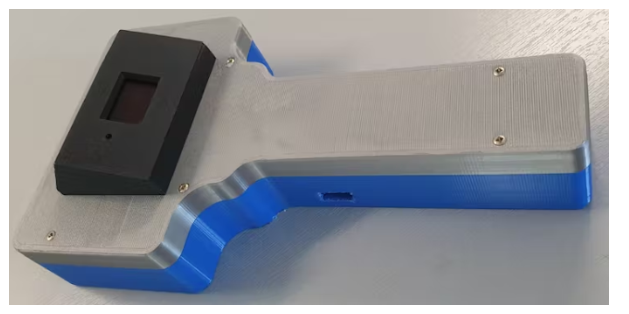
Step 2: Make the Geiger Counter Assembly
The following materials were used:
Arduino NANO 1
Geiger Counter Kit 1
0.96" OLED color display 96 * 64 1
Micro USB Charger Board 18650 Battery 1
3.7v 4000mAh Protected Rechargeable 18650 Li-ion Battery 1
Transistor BC547 1
Buzzer-12MM 1
Resistor 1k Ohm 1
Electronic Design
The electronic design of the Geiger counter kit is shown in the following circuit diagram:
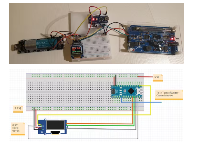
The circuit diagram for the complete Geiger counter setup is given below:
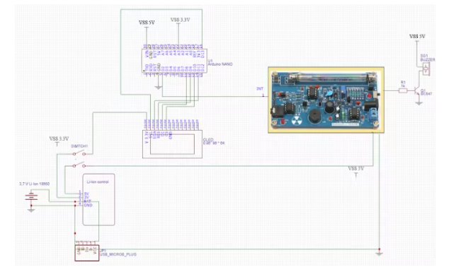
The 5V power supply is provided by a rechargeable Li-Ion battery placed on a Micro USB charger board. The 3,3 V for the OLED display is taken from this board.
The breadboard setup used to test and build the software using the ARDUINO IDE is shown in the image below:
Assembly
The assembly of all mechanical and electronic parts is shown in the following figure:
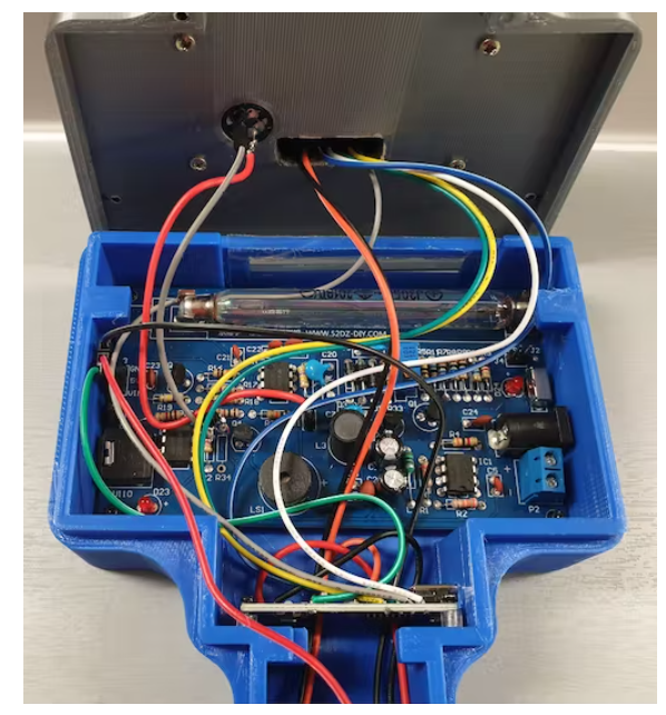
Please note that the handheld Geiger counter does not have any cables connected.
To charge the 3.7V Li-Ion battery, there is a separate opening in the housing for (temporary) connection of a micro USB plug.
An additional mini USB connection can be used for software updates of the Arduino Nano.
Step 3: Software Design
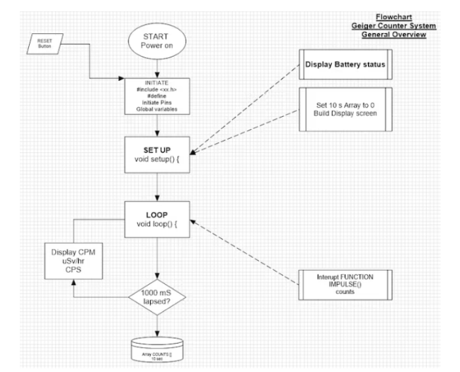
The following flow chart shows the general software design of a Geiger counter:
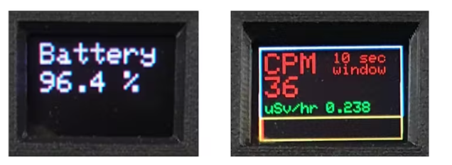
0, the view of the 96” OLED display is as follows:
The complete Arduino code is as follows:
#include
attachInterrupt(0, IMPULSE, FALLING);
The INT signal will start the interrupt routine IMPULSE() to increase Counts by 1:
void IMPULSE() {Counts++ ; }
After 1000 ms:
The integer Counts is set back to 0
The array COUNTS[ ] is filled with the counts measured in the last 1000 milliseconds.
The total count for the past 10 seconds is calculated by adding all the numbers in the array COUNTS[ ] and multiplying by 6 to show the CPM value on the display.
The dose equivalent expressed in µSv/hr is calculated by dividing the CPM value by 151 (this value can be found in the literature).
On the color OLED display, a red bar is shown according to the count value of the past second, so the CPS value (counts per second) is actually presented.
- Share a solar beacon circuit
- How to Design an Automatic IoT Egg Incubator Using ESP8266
- Tutorial on making a handheld Geiger counter
- Homemade CNC plotter
- IoT-based pet feeder
- Automatic recovery electronic fuse with soft start function
- Electronic Rat Killer Circuit
- How to build an internet-connected traffic meter
- Analysis of the circuit of DL-01 low-frequency electrotherapy instrument
- Detailed explanation of car battery charging circuit diagram
- Silent timer reminder circuit
- Adjustable precision stepper motor control circuit
- Simple three-phase brushless stepper motor drive circuit
- Coin-operated shooting game machine circuit
- LED display control circuit diagram in the counter
- Light intensity detection circuit diagram using counter
- High voltage Geiger counter power circuit
- CNC machine tool conversion counter and decoding circuit
- 4-digit LED display driver UP, DOWN counter
- Programmable counter


 京公网安备 11010802033920号