Share a solar beacon circuit
Source: InternetPublisher:红水杯 Keywords: Solar Updated: 2025/01/07
Beacons are used to guide travelers or mark important places or things. In the early days, fire and light were beacons for travelers as explorers. Nowadays, beacons have evolved from fire and light. While hiking, I noticed that officials installed a simple sound siren as a beacon at some places to guide hikers. I thought it was a good idea and it would be better if it was powered by solar energy, so built this solar beacon project.
Seeing as this, we also used similar beacons in a scavenger hunt on my college campus, where sound guided the players to the treasure. Hopefully you can find a similar application for this circuit.
General applications of beacons:
navigation
Guidance Purpose
vehicle
communication
Solar Beacon without Battery Backup:

In this circuit, the power comes directly from the solar panel. Therefore, this circuit will not work at night or when there is no sunlight (cloudy conditions). So I suggest you see if your application can tolerate this drawback.
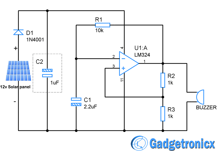
The circuit is powered by a 12v solar panel. It is able to supply 11.8v to the load in optimal sunlight and 11.4v to the load when the sunlight intensity is lower. The electrolytic capacitor C1 is used to stabilize the voltage output of the solar panel. The diode is used
D1 prevents current from flowing from capacitor C1
The current flows in the reverse direction to the panel. Considering the voltage drop of the diode is 0.7v, the final voltage output of the panel will be around 10.7v. This voltage is more than enough for our siren circuit.
Job Description:
The op amp acts as an astable multivibrator to generate a square wave. This in turn drives the buzzer. Hence, this forms the alarm portion of our circuit. After the circuit is powered on, the output of the op amp is unpredictable. Let us assume that the output is low, which is a logic "1". The output is fed back to the non-inverting input of the op amp through the voltage divider R2 and R3. Here, the input voltage at the + terminal of the op amp will be half of the supply voltage.
When the output is logic 1, capacitor C1 starts charging through feedback resistor R1. When the voltage in the capacitor exceeds the non-inverting terminal voltage, the output switches to logic 0. This causes the capacitor to discharge through R1.
When the output goes low, zero voltage will be present at the non-inverting terminal of the op-amp. Hence, when the capacitor is fully discharged and there is no voltage across C1, the op-amp again switches its state to 1. This cycle repeats and gives a square wave as output.
F = 1 / R1C1
This gives us a frequency of 20Hz as the output of the circuit.
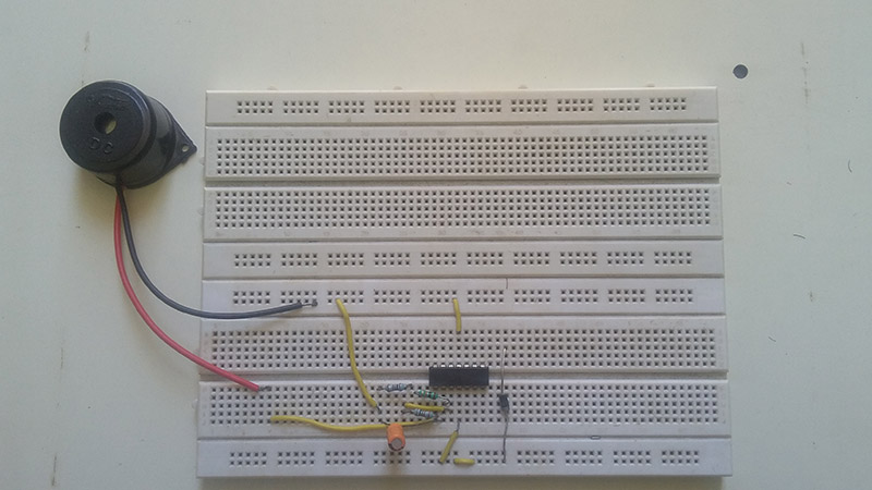
Breadboard Components:

Notice:
Cloud cover, lack of sunlight, and other external factors can interrupt circuit operation.
The circuit operates only during daylight hours.
The optional capacitor C2 is used to stabilize the input voltage level.
Solar Beacon with Battery Backup:

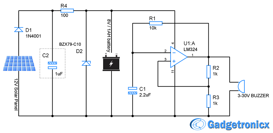
If you cannot tolerate the malfunction of this beacon at night and in cloudy conditions, you can use this circuit. The choice of battery is very important for this circuit. I recommend you to use 8v lead acid battery for this purpose.
To charge the battery:
Most 8V lead acid batteries need to be charged at about 9.4v to reach their maximum charge capacity. In addition, the supply current should be about 20% of its battery rated current. So, considering our battery
1Ah,20% – 200mA
That's enough to charge. The solar panel I'm using here is capable of providing that current so it won't be a problem. As I said before, this panel will provide 10.7v even in non-optimal conditions so I'll consider that for my calculations.
To regulate the voltage applied to the battery, I will use a simple zener diode which will provide a constant current charge to the battery at a fixed voltage. The zener diode BZX79-C10 is rated at 9.4v. So to determine R4
R = (Vin – Vz) / (Iz + IBat)
R = 10.7 – 9.4 / ( 50mA + 200mA )
R = 100 ohms (approximate standard resistor value)
So this setup will safely charge an 8v lead acid battery via the solar panel.
Battery discharge:
Now let's see how much current our beacon actually consumes.
I = IBuzzer + IR (current through voltage divider R2 and R50 at 3% duty cycle)
I = 15mA (from datasheet) + 10.7 / 2K @50%
I = 15mA + 2.67mA
I = 17.6mA.
However, to be safe, let's consider 30mA as the current drawn from the battery. So the circuit will require 30mA, which will provide 30mAh for one hour of use. So this battery will barely power the circuit for about 25 hours, but still leave 25% of the charge in the battery.
This is pretty much theoretical, but in reality not everything works out according to your math. You can't count on having sunlight for the entire usage day. So the best guess is that you can run the beacon in real time for about 20 seconds before recharging.
hours, even though your math gives 25 hours before draining the battery 25%. Also, it's best to only use lead acid batteries up to 75% charge to extend battery life.
Also, it is always good to know the charge level of the battery. Here is a guide to building your own lead acid battery charge indicator circuit. The rest of the circuit is the same as the circuit without the backup battery. Refer to that instructable.
Notice:
Mathematical calculations are always performed taking into account the uncertainty of atmospheric conditions that affect solar energy.
Go through your battery datasheet thoroughly to understand your battery's specifications, it may be different.
Capacitor C2 is used to stabilize the output voltage of the solar panel.
- IoT-based weather data logger
- How to use Tesseract for optical character recognition on Raspberry Pi
- How to connect TFT LCD to Raspberry Pi
- Design of a drone wildlife counting system using FOMO object detection algorithm
- DIY a simple weather station
- Production of electric mosquito killer
- How to use the MP3 player from CATALEX
- Input and output polarity reversal circuit composed of MAX660
- Detailed explanation of car battery charging circuit diagram
- Design of TinyML Image Classification Camera Based on ESP32
- Application and layout analysis of solar energy and electric vehicle charging systems
- Single solar battery charger working circuit
- Solar flasher principle circuit
- Novel solar LED light controller circuit diagram
- Solar LED light circuit
- Solar flasher principle circuit
- Solar flashlight supercapacitor storage circuit
- All-weather solar automatic tracking controller circuit
- Solar automatic tracking controller circuit
- Hefei Sunshine Solar and Wind Power SD Intelligent Controller


 京公网安备 11010802033920号