Share a project that controls the mouse pointer by moving the index finger
Source: InternetPublisher:清宁时光 Keywords: Mouse control MPU6050 Updated: 2024/12/31
This is my first project, ThimbleKrox, it's a thimble that allows you to control your mouse pointer with the movement of your index finger (or any finger).
Step 1: Materials and Tools Required
Materials Needed:
Arduino Micro
MPU-6050
Cable for connecting Arduino and PC (micro USB to USB)
Jumper wires (to connect Arduino and MPU-6050)
An elastic band (if you want to attach the Arduino to your hand)
Tools Required:
A computer with the Arduino IDE installed (for launching the code in Arduino)
Soldering iron (only if the Arduino does not come pre-assembled with pin connectors)
3D printer (if you want your ejector pin to look cool)
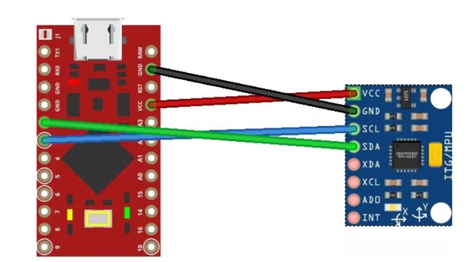
Step 2: Connect
Connect the pins of arduino to the pins of MPU-6050:
Pin VCC of Arduino to pin VCC
Pin GND to GND
Pin 2 to SDA
Pin 3 to SCL.

Step 3: 3D Printing (Optional)
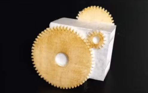
If you want your ejector pin to look nice, and if you have a 3D printer, you can print a physical ejector pin.
I made two versions, one is transparent so it doesn't need print supports and is less bulky, the second is my attempt to do it in a steampunk style without making it too bulky (it's still bulkier than the transparent one), but this one needs print supports and only returns best when in color (for PLA, I get along just fine with tempera). Both need to be printed with the part on the bottom that has two internal protrusions

Step 4: Assembly
Using 3D Printed Ejector Pins
To mount everything using the printed ejector pins, once connected, the MPU-6050 must be inserted into the upper cavity of the ejector pins, housing the cable in the lower cavity.
No 3D printed ejector pins
In this case, the assembly is done in a more amateur way, i.e., the MPU-6050 is placed in the last square of the finger of interest and blocked with tape or elastic.
Step 5: Encoding and Calibration
The first thing to do to run the code is to install the required libraries, namely Wire.h, I2Cdev.h, MPU6050.h, and Mouse.h
Once this is done, I recommend loading the ThimbleKrox calibration code, putting on the thimble and opening the serial monitor (Ctrl+Shift+M).
You should now see something like this:
right | gx = 3165 gy = 469 gz = -1055 | ax = 15232 ay = 2064 az = -4496
The direction you want the pointer to move is shown if calibrated correctly, followed by some values required for the calibration.
Now you have to reopen the code and go to the line labeled "//Calibration Lines" and change the values until you get the correct direction. (Every time you change a value in the code you will need to re-upload in the Arduino)
Serial Monitor:
left | gx = 3165 gy = 469 gz = -1055 | ax = 5232 ay = 2064 az = -4496
Calibration Code:
if (ax> = 15000) { // calibration line
right ();
}
The serial monitor is labeled "Left", but we want this line to be labeled "Right", so we need to change the "15000" value to "5000". This is because, in this case, we have to make sure that the "ax" detected is greater than the value in the code. We know it has to be greater because in the code there is a major sign and we have to look at the serial monitor for "ax" because there is "ax" in the code. (Just change the numerical value of the code)
After reloading the code in Arduino we will have:
Serial Monitor:
right | gx = 3165 gy = 469 gz = -1055 | ax = 5232 ay = 2064 az = -4496
Calibration Code:
if (ax> = 5000) { // calibration line
right ();
}
When all the calibration lines in the calibration code have been adjusted so that the calibration version ejector pin is functional, the value of the master code must be adjusted to match the calibration code.
Calibration Code:
if (ax> = 5000) { // calibration line
right ();
}
Main code:
if (ax> = 15000) { // calibration line
right ();
}
The main code must be changed to:
if (ax> = 5000) { // calibration line
right ();
}
Now it's time to upload the main code
Step 6: Finishing the Project
Now it's time to put your fingers on the mouse and play PC games with it!
ThimbleKrox code:
//Code to control the mouse pointer through the movement of a finger
//To calibrate the device run "ThimbleKrox calibration code" and follow the tutorial found at https://www.hackster.io/projects/dd8881/
//The lines that need to be changed f or calibration have "//calibration line"
//code write by Magform
#include
MPU6050 mpu;
int16_t ax, ay, az, gx, gy, gz;
int vx, vy;
int sensibility=10; //Change this value to change the sensitivity of the device
void setup() {
Serial.begin(9600);
Wire.begin();
mpu.ini tialize();
if (!mpu.testConnection()) { //check connection with the MPU-6050, if there is no connection stop to work
while (1);
}
}
void up(){
Mouse.move(0, -sensibility);
}
void down(){
Mouse.move(0, sensibility);
}
void left(){
Mouse.move(-sensibility, 0);
}
void right( ){
Mouse.move(sensibility, 0);
}
void loop() {
mpu.getMotion6(&ax, &ay, &az, &gx, &gy, &gz);
if(ax>=15000){ //calibration line
right();
}
if(ax<=-9000){ // calibration line
left();
}
if(ay<=-8000){ //calibration line
up();
}
if(ay>=10000){ //calibration line
down();
}
//uncomment the following lines to set the right click with a sprint up and the left click with a sprint down (Work in progress part)
/*
if(gy>=20000){ //calibration line
Mouse.click(MOUSE_RIGHT);
delay(100);
}
if(gy<=-20000){ //calibration line
Mouse.click(MOUSE_LEFT);
delay(100);
}
*/
delay(10);
}
- How to Make a Bass Boost Speaker Box
- IoT-based weather data logger
- Build a Raspberry Pi-based QR code scanner
- How to implement semaphores and mutexes in FreeRTOS using Arduino
- Tutorial on making a handheld Geiger counter
- Homemade CNC plotter
- Building a Dehumidifier for a 3D Printing Dry Box
- How to build an autonomous robot using the DonkeyCar platform
- Working Principle and Production of TV Scanning Demonstrator
- Making an Off-Grid Solar PV System
- How does an optocoupler work? Introduction to the working principle and function of optocoupler
- 8050 transistor pin diagram and functions
- What is the circuit diagram of a TV power supply and how to repair it?
- Analyze common refrigerator control circuit diagrams and easily understand the working principle of refrigerators
- Hemisphere induction cooker circuit diagram, what you want is here
- Circuit design of mobile phone anti-theft alarm system using C8051F330 - alarm circuit diagram | alarm circuit diagram
- Humidity controller circuit design using NAND gate CD4011-humidity sensitive circuit
- Electronic sound-imitating mouse repellent circuit design - consumer electronics circuit diagram
- Three-digit display capacitance test meter circuit module design - photoelectric display circuit
- Advertising lantern production circuit design - signal processing electronic circuit diagram


 京公网安备 11010802033920号