What are the classifications of filters?
Source: InternetPublisher:elleny Keywords: Filters frequency devices Updated: 2025/01/14
What is a filter
A filter is a frequency selective device that allows certain frequency components of a signal to pass through and greatly attenuates other frequency components. In a test setup, the frequency selection function of a filter can be used to filter out interfering noise or perform spectrum analysis. Broadly speaking, any information transmission channel (medium) can be considered a filter. Since the response characteristics of any device are a function of the excitation frequency, these transmission characteristics can be described by frequency domain functions. Therefore, any part of the test system, such as mechanical systems, electrical networks, instrumentation, and even connecting lines, will transform and process signals passing through a certain frequency range according to its frequency domain characteristics.
According to the nature of the filter signal processing, filters are divided into analog filters and digital filters.

Filter Classification
2.1 Classification based on filter frequency selection
Low pass filter
From 0 to f2, the amplitude-frequency characteristic is flat, so that the frequency components below f2 in the signal are almost not attenuated, while the frequency components above f2 are greatly attenuated.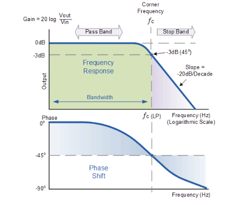
High Pass Filter
Compared with low-pass filtering, the amplitude-frequency characteristic is flat from frequency f_1 to ∞, which allows frequency components above f_1 to pass almost without attenuation, while frequency components below f_1 are greatly attenuated.
Bandpass filter
The passband of the bandpass filter is between f1 and f2. It allows the frequency components above f1 and below f2 in the signal to pass without attenuation, while other components are attenuated.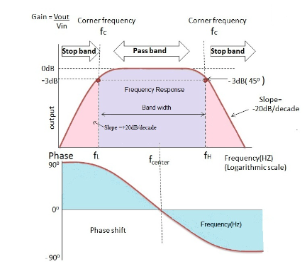
Bandstop filter
Compared with bandpass filtering, the stop band of the bandstop filter is between frequencies f1 and f2. It attenuates the frequency components above f1 and below f2 in the signal, and passes the remaining frequency components with almost no attenuation.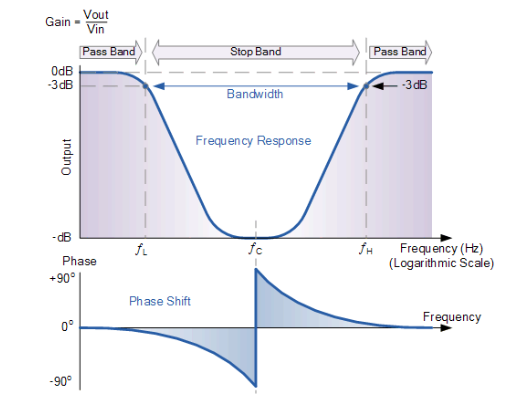
Notice
Low-pass filter and high-pass filter are the two most basic forms of filters. Other filters can be divided into these two types of filters. For example, the series connection of low-pass filter and high-pass filter is a band-pass filter; the parallel connection of low-pass filter and high-pass filter is a band-stop filter.
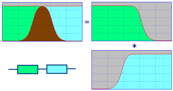
The series connection of low pass filter and high pass filter
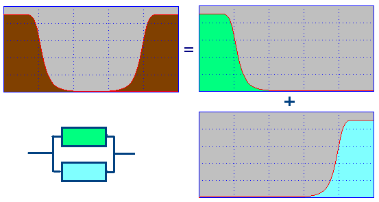
Parallel connection of low pass filter and high pass filter
2.2 Classification based on the “best approximation property” criterion
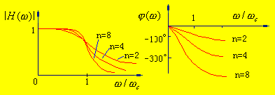
Butterworth filter
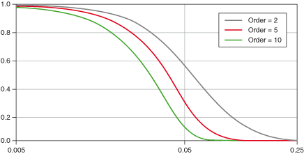
The requirements for the Butterworth filter will be based on the amplitude-frequency characteristics without considering the phase-frequency characteristics. The Butterworth filter has the characteristic of maximum flat amplitude. The amplitude-frequency response expression is:
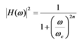
In is the order of the filter; WC is the cutoff frequency of the filter,
When w=wc, |H(wc)|2=1/2, so wc corresponds to the -3db point of the filter.
The Butterworth low-pass filter uses the Butterworth function as the filter transfer function H(s) and approximates the ideal rectangular shape of the filter in the form of a highest-order Taylor series.
Chebyshev filter
The approximate requirements of the Chebyshev filter are also proposed from the amplitude-frequency characteristics. The amplitude-frequency response expression is:

ε is the fluctuation coefficient that determines the size of the passband ripple, 0 <ε <1. The ripple is due to the presence of reactive components in the actual filter network; wc is the passband cutoff frequency, and Tn is the nth-order Chebyshev polynomial.
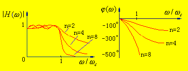
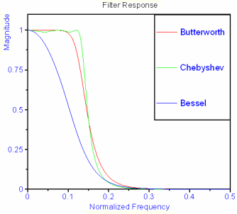
Compared with the Butterworth approximation, although the characteristic fluctuates within the passband, after entering the stopband, for the same n value, its attenuation is larger and closer to the ideal situation. The smaller the ε value, the smaller the fluctuation within the passband. At the same time, the decibel value of the attenuation at the cutoff frequency will also become smaller, but the attenuation characteristics after entering the stopband will slow down. Compared with the Butterworth filter, there are ripples in the Chebyshev filter passband, and the transition band of the Chebyshev filter is slightly steep; therefore, when ripples are not allowed in the passband, the Butterworth filter is more ideal.
From the perspective of phase response, the Butterworth type is better than the Chebyshev type. From the above two comparisons, it can be seen that the phase-frequency response of the former is closer to a straight line.
From the perspective of phase-frequency response, the Butterworth type is better than the Chebyshev type. By comparing the two figures below, it can be seen that the phase-frequency response of the former is closer to a straight line.
Bessel filter
Only the phase-frequency characteristic is satisfied, and the amplitude-frequency characteristic is not concerned. Bessel filter, also known as the flattest time delay or delay filter. The phase shift is proportional to the frequency, that is, a linear relationship. However, due to its poor amplitude-frequency characteristic, its application is often limited.
2.3 Classification according to the properties of filter components
Passive filter (R, L, C)
Active filters (including operational amplifiers)
- How to calculate the value of capacitors in parallel?
- What is power factor and three ways to improve it
- DIY a decorative lamp
- Share an interesting LED decoration project
- Ceramic filter structure/working principle/characteristics/application
- Build a musical fountain using Arduino and sound sensor
- What is the difference between high-side and low-side resistive current sensing
- Odd-frequency counter with symmetrical output waveform (μL9020)
- Demonstration device for capacitor charging and discharging process
- How to make a four-level water level indicator with full water alarm function
- 20Hz High Pass Turntable Noise Filter
- 555 square wave oscillation circuit
- 555 photo exposure timer circuit diagram
- Introducing the CD4013 washing machine timer circuit diagram
- Simple level conversion circuit diagram
- 555 electronic guide speaker circuit diagram for blind people
- Circuit diagram of disconnection alarm composed of 555
- Analog circuit corrector circuit diagram
- color discrimination circuit
- Color sensor amplification circuit


 京公网安备 11010802033920号