Working principle/advantages/disadvantages/size of optical fiber
Source: InternetPublisher:闪电杰克 Keywords: Fiber Optic Fiber Optic Technology Updated: 2025/01/07
For decades, electronic signals have been sent very successfully over standard "hardwired" connections or using different types of radio links which have a number of disadvantages.
On the other hand, fiber optic links, whether used for audio or video links over long distances or for handling small distances, offer some distinct advantages over regular wired cables.
How Fiber Optics Work
In fiber optic circuit technology, optical fiber links are used to transmit digital or analog data in the form of optical frequencies through a cable with a highly reflective central core.
Internally, optical fiber consists of a highly reflective central core that acts like a light guide, transmitting light by continuously bouncing back and forth off its reflective walls.
Optical links typically include an electrical-to-optical frequency converter circuit that converts the digital or audio signal to an optical frequency. This optical frequency is "injected" into one end of the optical fiber by a powerful LED. The light is then allowed to travel through the fiber optic cable to the intended destination, where it is received by a photocell and amplifier circuit that converts the optical frequency back to the original digital form or audio form.
Advantages of Fiber Optics
A major advantage of fiber optic circuit links is their perfect immunity to electrical interference and stray pickup.
Standard "cable" links can be designed to reduce this problem, but eliminating it completely can be very challenging.
Conversely, the non-electrical nature of fiber optic cables helps to make electrical interference insignificant, except for some interference that can be picked up at the receiver end, but this can also be eliminated by effectively shielding the receiver circuitry.
Likewise, broadband signals routed over conventional cables often pick up electrical interference, causing interference with nearby radio and television signals.
But again, in the case of fiber optic cable, it does demonstrate a complete lack of electrical radiation, and even though the transmitter unit may emit some RF radiation, it is fairly simple to enclose it using basic shielding strategies.
Due to this advantage, systems containing many optical cables operate adjacent to each other without the complications or problems of crosstalk.
Of course, light may leak from one cable to another, but fiber optic cables are usually enclosed in a light-proof outer casing that ideally prevents any form of light leakage.
This strong shielding in fiber optic links ensures a fairly safe and reliable data transmission.
Another advantage is that fiber optics do not have fire hazard issues because there is no electricity or high currents involved.
We also have excellent electrical isolation throughout the link to ensure that ground loop complications do not develop. With appropriate transmit and receive circuitry, it is well suited for fiber optic links to handle a large bandwidth range.
Broadband links can also be created over coaxial power cables, although modern fiber optic cables generally have lower losses than coaxial types in wide bandwidth applications.
Fiber optic cables are generally thin and lightweight, and are not affected by climatic conditions and several chemicals. This often allows them to be quickly applied in inhospitable environments or adverse situations where cables, especially coaxial types, would prove to be quite ineffective.
Disadvantages
Although fiber optic circuits have many advantages, they also have some disadvantages.
The obvious disadvantage is that electrical signals cannot be transmitted directly into optical cables, and in some cases the cost and problems encountered with significant encoder and decoder circuitry are often highly incompatible.
A key thing to remember when working with optical fibers is that they usually have a specified minimum diameter, and when they are twisted in a sharper curve, physical damage can occur to the cable at that bend, rendering it useless.
The "minimum bend" radius usually stated in data sheets is usually between about 50 and 80 mm.
In ordinary wired power cables, the consequences of such bends may be negligible, but with fiber-optic cables, even small tight bends can hinder the propagation of light signals, resulting in drastic losses.
Fiber Optic Basics
While it may seem to us that fiber optic cables consist of nothing more than strands of glass covered in a light-proof outer casing, things are actually much more advanced than that.
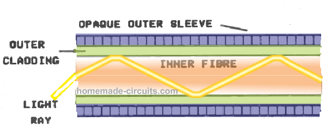
Nowadays, glass strands are mostly in the form of polymers rather than actual glass, and a standard setup might look like the image below. Here we can see a central core with a high refractive index and an outer shield with a reduced refractive index.

Refraction from the interaction of the inner filaments and the outer cladding allows light to travel through the cable by efficiently going from wall to wall in the cable.
It is this reflection of light off the cable walls that allows the cable to operate like a light guide, carrying lighting smoothly around corners and curves.
High-order mode light propagation
The angle at which the light is reflected is determined by the properties of the cable and the angle at which the light is input. In the image above you can see that the light is propagating through "higher order modes".
Low-order mode light propagation
However, you'll notice that the cable has a shallow angle for the light, causing it to bounce between the cable walls at a fairly wide angle. This lower angle allows the light to travel a relatively long distance through the cable on each bounce.
This form of light transmission is called "low-order mode" propagation. The practical significance of these two modes is that light venturing through the cable in the higher-order mode needs to travel significantly further than light propagating in the lower-order mode. This can smear the signal transmitted through the cable, thereby reducing the frequency range of the application.
However, this is only relevant in very wide bandwidth links.
Single mode cable
We also have "single mode" type cables which are used to enable only a single mode of propagation, but this form of cable is not actually required to use the relatively narrow bandwidth techniques detailed in this article. You may further come across another type of cable called "graded index" cable.
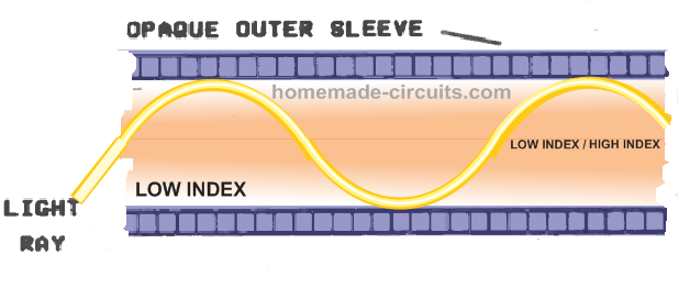
This is actually very similar to the step-index cable discussed earlier, although there is a gradual transition from a high index near the center of the cable to a decreasing value near the outer jacket.
This causes light to travel through the cable in a very similar way to that explained previously, but instead of traveling in a straight line, the light has to take a curved route (as shown in the image below).

Fiber size
The typical size of a fiber optic cable is 2.2 mm, with the average size of the inner fiber being about 1 mm. In addition to many systems connecting to the same matching cable, you can also find multiple connectors to connect with cables of this size.
The common connector system consists of a "plug" that fits over the tip of the cable and secures it to a "socket" terminal, which is usually mounted on a circuit board and has a slot to accommodate a photocell (the emitter or detector that forms the optical system).
- Why Do Amplifier Fuses Blow? How Do You Prevent Amplifier Fuses from Blowing?
- What is a D flip-flop and how does it work?
- Why use PWM? What are its advantages?
- Share a Motorola amplifier circuit
- Touch circuit design and analysis
- Star finder battery indicator circuit
- Using Monostable Trigger to Construct Pulse Delay Circuit
- 915MHz RF amplifier circuit composed of RF2103P
- UHF amplifier circuit
- Unity-gain buffer circuit composed of MAX4100/MAX4101
- Highly sensitive optical fiber receiving amplifier
- Laser transmitter and sending circuit
- DC variable speed motor controller circuit diagram using optical fiber
- Optical fiber interface circuit diagram
- Optical fiber receiving circuit
- Optical fiber rain detection circuit
- Optical fiber vibration measurement detection circuit
- Practical circuit for flow continuous analysis based on luminescence fiber optic biosensor
- Photoelectric coupling and amplification circuit of fiber optic flow sensor
- 555 square wave oscillation circuit


 京公网安备 11010802033920号