Current output characteristics of brushed motor driver chips. How to increase the peak drive current?
Source: InternetPublisher:张三叔 Keywords: MOSFET brushed motor Updated: 2025/01/16
In recent years, with the enhancement of people's health awareness, the expansion of the sub-healthy, elderly Chinese, business travel and office groups, and the continuous updating and upgrading of intelligent massage chair products, massage chairs with good massage and health care effects are gradually gaining recognition from consumers. From the perspective of motor types, brushed motors have always dominated the speed regulation field due to their simple control methods and excellent torque control characteristics. In order to increase power, the drive in the massage chair often uses a 12/24V brushed motor. Considering the transient voltage during motor operation, a driver chip with a withstand voltage range of 40-50V is often used.
This article will focus on the current output stage characteristics of TI's brushed motor driver chip with integrated MOSFET, and how to enhance the drive peak current.
Current output of brushed motor driver chip

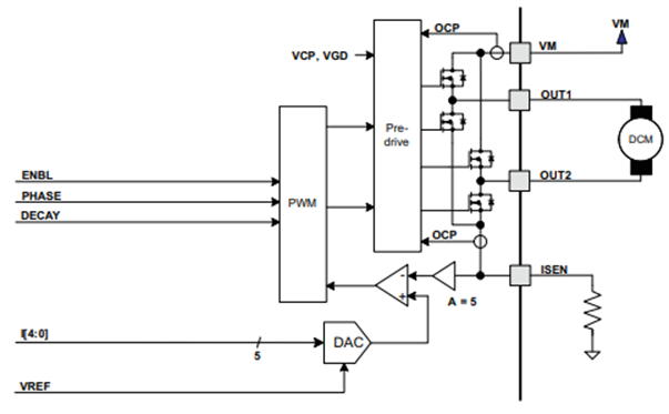
Figure 1: DRV8840 output stage
Since heavy-load starting or high-torque operation is often encountered in the use scenarios of massage chairs, the output current part of the brushed motor drive is analyzed below:
The speed of the brushed motor is determined by the voltage applied to the motor armature, and the direction is controlled by the H-bridge integrated inside the chip. The faster the speed, the greater the back electromotive force generated. In the following formula, I is the current flowing through the motor coil, U is the voltage applied to the motor, E is the back electromotive force, and R is the coil resistance.

When the motor is stalled or just started, the speed is 0 and the back electromotive force is 0. At this time, the current is the largest, which corresponds to the load capacity of the driver chip. In order to avoid excessive current burning the motor when stalled, TI's BDC driver chips all have a current limiting function. Taking DRV8840 (Figure 1) as an example, a sampling resistor is connected in series to the ISEN pin, and this voltage is compared with the reference voltage VREF to obtain the current limiting threshold:

This large current will pass through the Rsense sampling resistor, which is often a milliohm-level power resistor that occupies a large board area. In some applications of massage chairs, this current value needs to be collected to determine the output torque of the motor. At this time, an additional op amp is required to increase the input impedance of the ADC, and then the current is collected through the ADC. In traditional brushed motor drive applications, this method is the most common and occupies the largest PCB area.
New features of brushed motor driver IC
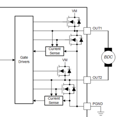
In TI's latest 50V withstand voltage brushed motor driver chips, such as the DRV8256 (Figure
2) The current mirror technology is used internally. During startup and high load events, the integrated current sensing can adjust the motor inrush current through the driver. Combined with the adjustable external voltage reference Vref, the current limit can be set.
This technology does not require a high-power shunt resistor, which can save circuit board area and reduce system costs, but it also loses the current path reserved for the outside, so it is not suitable for some occasions where the total current needs to be collected. It is worth noting that it is not possible to connect a sampling resistor in series between the OUT1 and OUT2 pins. This current changes in both directions, and the common-mode voltage to the ground is also very high. There is no need to introduce an additional floating op amp and power supply. It is also not recommended to connect a sampling resistor in series between the PGND pin and the ground, as this will destroy the potential difference between PGND (power ground) and GND (logic ground), causing control logic errors.

Figure 2: DRV8256 output stage
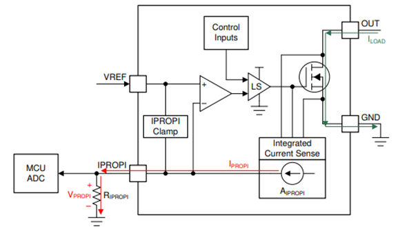
Or, referring to TI's other brushed motor driver chip DRV8251A (Figure 3), the current mirror inside the chip will mirror the current through the lower MOSFET into a current source, reduce it by a factor of AIPROPI (uA/A), and convert it into a voltage value VIPROPI through a large resistor (kΩ) externally connected to the IPROPI pin, and then connect it to the input of the ADC for current acquisition. This proportional current mirror method not only saves a large sampling resistor of the mΩ level, but also the sampling voltage generated by the internal current source is dedicated to the sampling resistor, and the input impedance is large enough to directly enter the ADC sampling terminal.

Figure 3: DRV8251A output stage
Connect driver chips in parallel to increase load capacity
Since TI's brushed motor driver chip has a built-in MOSFET, Rds-on determines the heat generated when continuous current passes through. When the temperature rise exceeds the temperature limit, the chip will be forced to enter OTP protection and autoretry after the temperature drops or a fixed time. When the current demand of the load exceeds the current peak of a single brushed motor driver chip, in addition to selecting a larger package and optimizing the heat sink layout, there is also a method of connecting driver chips in parallel to increase the current output capability.
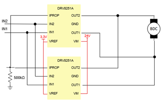
As shown in Figure 4: When two identical DRV8251A input and output stages are connected in parallel, the current will be evenly distributed to the H-bridges inside the two chips, increasing the output drive capability without triggering overcurrent protection.

Figure 4: Parallel connection of DRV8251A improves current output capability
There are two points to note when adjusting the chip current limit value:
The chip current limit mentioned above is determined by the voltage comparison on the IPROP and Vref pins. Generally, the same 3V power rail is used to power the Vref pin. If the current of two chips is sampled separately, and the sampling resistor uses a common 1% precision chip resistor, it will often introduce an error of up to 2% on the IPROP pin, which means that the current limit values of the two chips are different.
The internal resistance of the MOSFET of the H-bridge in different chips is not completely consistent. If only the input and output pins are connected in parallel, the current will not flow evenly to the two chips. Combined with the above two points, the driving capabilities of two chips with different current limiting values are not simply additive. When one chip enters the current limiting state due to excessive load, it will cause the other chip to enter the current limiting state as well.
A simple solution is to power the Vref pins of the two chips with the same power rail and connect the IPROP pin to the same sampling resistor. This ensures that the current limit values of the two chips are the same and the output currents are linearly related.
- Analysis of the working principle of car garage door lights
- The meaning and importance of circuit protection, common types of circuit protection
- How to Make a Simple 2-Step Arduino Programmable Timer Circuit
- How to Make a Simple Chicken Incubator
- What is a RADAX motor?
- JDB-LQ-TQ/2 motor full voltage starting circuit
- IGBT modules block overcurrent by controlling the gate
- Design and analysis of touch delay switch circuit composed of CD4011 and CD4001
- Design and production of no-load automatic power-off device for household power supply
- Homemade short circuit alarm device
- Microwave oven control circuit
- Haier KFR-25GW air conditioner control circuit schematic diagram
- Galanz rice cooker control circuit
- Humidity detection box control circuit in greenhouse
- Automatic sprinkler irrigation control circuit
- Steam iron temperature detection control circuit
- Micro DC motor steady speed control circuit b
- Micro DC motor steady speed control circuit a
- Temperature detection control circuit for vegetable greenhouses
- Simple V-MOSFET dimmer circuit


 京公网安备 11010802033920号