Basic characteristics of power field effect tubes, how to improve the dynamic performance of power MOSFET
Source: InternetPublisher:spectrum Keywords: MOSFET power field effect tube Updated: 2025/01/21
Basic characteristics of power field effect tube
Static characteristics
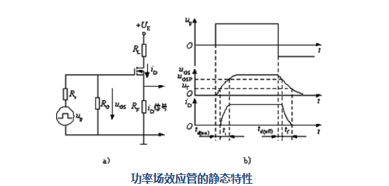
The transfer characteristics and output characteristics of static characteristics are shown in the figure. (a) is the transfer characteristic and (b) is the output characteristic.

Static Characteristics of Power Field Effect Transistors
The relationship between the drain current ID and the gate voltage UGS is called the transfer characteristic of the MOSFET. When ID is large, the relationship between ID and UGS is approximately linear, and the slope of the curve is defined as the transconductance Gfs.
The drain-ampere characteristics (output characteristics) of MOSFET: cut-off region (corresponding to the cut-off region of GTR); saturation region (corresponding to the amplification region of GTR); unsaturation region (corresponding to the saturation region of GTR). The power MOSFET works in a switching state, that is, the transition between the cut-off region and the unsaturation region. There is a parasitic diode between the drain of the power MOSFET. When the drain is connected to the reverse voltage, the device is connected. The on-resistance of the power MOSFET has a positive temperature coefficient, which is conducive to current sharing when the devices are connected in parallel.
3 Dynamic characteristics
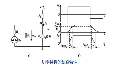
The test circuit and switching process waveform of the power MOSFET dynamic characteristics are shown in Figure 1. (a) is the test circuit, and (b) is the switching process waveform.

Dynamic characteristics of power characteristics
The start-up process is as follows: start-up delay time TD (start-up) - the start time interval between the time forwarded upward to uGS=UT and iD.
Rise time tr - the gate pressure UGSP time from uGS rising from uT to MOSFET entering the non-saturation region.
The steady-state value of iD is determined by the drain supply voltage UE and the drain load resistance. The size of UGSP is related to the steady-state value of iD. When UGS reaches UGSP, it continues to rise until it reaches a steady state, but iD does not change.
The turn-on time is ton -- the sum of the turn-on delay time and the rise time.
Turn-off delay time TD(turn-off) - Decreases upward to zero, Cin discharges through Rs and RG, uGS decreases exponentially to UGSP, and iD starts to decrease to zero.
Descending time TF - uGS decreases from UGSP and iD decreases to uGS.
Turn Off Time Turn Off - Turn off delay time and fall time.
The switching speed of the FET
The switching speed of MOSFET has a lot to do with the charging and discharging of Cin. Users cannot reduce "Cin", but they can reduce the internal resistance Rs of the driving circuit, reduce the time constant, and speed up the switching speed. MOSFET only relies on multi-phonon conduction and has no small son storage effect, so the shutdown process is very fast, and the switching time is between 10 and 100ns, which can reach the operating frequency. Above 100kHz is the highest among the main power electronic devices.
Field control equipment is static and has almost no input current. However, during the switching process, the input capacitor needs to be charged and discharged, which still requires a certain amount of drive power. The higher the switching frequency, the greater the required drive power.
How to Improve the Dynamic Performance of Power MOSFET
In addition to the voltage, current and frequency of the device, the device must be used to protect the device in the application, and the device will not be damaged in transient changes. Of course, the thyristor is a combination of two bipolar transistors, plus the large capacitance brought by the large area, so its dv/dt capability is relatively fragile. For di/dt, there is also the problem of enlarged conduction area, so it also brings quite strict restrictions.
The situation is quite different for the power MOSFET. Its dv/dt and di/dt capabilities are usually estimated by the capability per nanosecond, not per microsecond. However, it also has limitations in terms of dynamic performance. These can be understood from the basic structure of the power MOSFET.
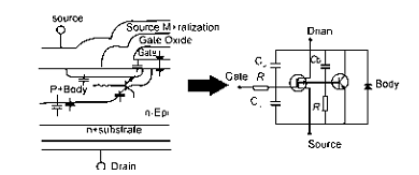
The figure below shows the structure and equivalent circuit of a power MOSFET. In addition to the capacitance of almost every part of the device, we must also consider that the MOSFET is connected in parallel with a diode. At the same time, from a certain perspective, it still has a parasitic transistor. (Like IGBT is also a parasitic thyristor). These aspects are very important factors in studying the dynamic characteristics of MOSFET.

- Benefits of Wide Bandgap Technology for Power Converters
- Basic circuit description of adjustable voltage regulator LM317
- INA155/INA156 is used to form a single-supply high-side current monitor for detecting load current
- Detailed explanation of 5v charger circuit diagram
- How to use SBR to improve power conversion efficiency
- A novel and practical DC low voltage stabilized power supply
- 3~15V 10A adjustable voltage regulated power supply
- Car power 1.5V-12V six-speed converter
- MAX1811 Lithium Battery Charger Production
- A low-cost, high-reliability battery charger for electric vehicles
- 24V power supply pure flat display high voltage power supply circuit diagram
- Power circuit b composed of intelligent thyristor modules
- Laser power circuit
- EPSON PHOTO 830U printer power circuit
- Commonly used power circuits in printers
- audio power circuit
- Simple V-MOSFET dimmer circuit
- Remote control TV doorbell power circuit
- ±15V active servo power circuit
- AC-DC conversion power supply-inverter power supply circuit


 京公网安备 11010802033920号