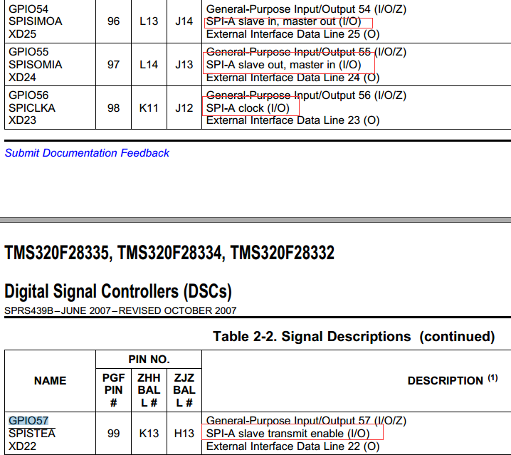
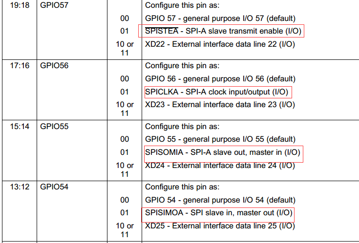
|
The OP
Published on 2020-1-5 18:27
Only look at the author
This post is from DSP and ARM Processors
| ||
|
|
||
- 【Posts】TMS320F28335——SPI usage notes
- 【Posts】TMS320F28335 Study Notes - Clock
- 【Posts】TMS320F28335 Study Notes——DMA
- 【Posts】TMS320F28335 Study Notes - Startup Process
- 【Posts】tms320f28335
- 【Posts】TMS320F28335 Study Notes - Startup Process
- 【Posts】Please help! Does anyone have a solution for the TMS320F28335 chip being locked?
- 【Posts】TMS320F28035/TMS320F28335 cannot capture low-frequency signals
- 【Download】TMS320F28335 chip internal and external devices_CAN, SPI
- 【Download】Design and implementation of solar power generation simulation system based on TMS320F28335 source code
- 【Download】Source code of parallel power supply system of switching power supply module based on TMS320F28335
- 【Download】Development source code of high performance variable frequency speed regulation system based on TMS320F28335 control
- 【Download】TI TMS320F28335 chip Chinese manual
- 【Download】TMS320F28335 minimum circuit diagram PCB diagram
- 【Download】TMS320F28335 development routines, including USB, serial port, AD, DA
- 【Download】TMS320F28035 DSP development board experiment SPI_nRF24L01
- 【Design】Design and implementation source code of solar power generation simulation system based on TMS320F28335
- 【Design】Source code of switching power supply module parallel power supply system based on TMS320F28335
- 【Design】Development source code of high-performance frequency conversion speed regulation system based on TMS320F28335 control
- 【Articles】Discussion on the Design of Microgrid Phase-Locked Loop Based on TMS320F28335
- 【Articles】Application of TMS320F28335 in Power Grid Frequency Measurement
- 【Articles】Application of TMS320F28335 in power grid frequency measurement (Part 2)
- 【Articles】Application of TMS320F28335 in power grid frequency measurement (I)
- 【Articles】Take you to understand TI's DSP entry chip TMS320F28335
- 【Articles】Design of Two Booting Methods for TMS320C6727 DSP
-
TMS320F28335 Study Notes - Clock
Whenusinganactivecrystaloscillatorasanexternalclocksource,thecrystaloscillatorcircuitintheDSPchipwillbebypassed,andtheexternalclocksignalisinputtotheDSPthroughtheXCLKINpinTheC28xcoreconvertstheinputCLKINsignalintotheSYSCLKOUTsignal(thisisth ...
-
TMS320F28335 Study Notes——DMA
TheSPR530(C2833x/C2823xC/C++headerfilesandperipheralexamples)providedbyTImakesitveryconvenientforustousetheperipheralsof2833Xand2823X//$TIRelease:DSP2833xHeaderFilesV1.10$//$ReleaseDate:February15,2008$//DefinedinDSP2833x_Adc/voidInitAdc(vo ...
-
OPEN SCOFIELD WINTER WARDROBE
[img]https://wwwnet/images/2024/11/14/1f9dff95d3bc981f8img][img]https://wwwnet/images/2024/11/14/2a81ca07f0c52991bimg]
- Newbie Report Newbie Report
- How to use CAN communication to control the inverter?
- FPGA Design Process
- Sharing of key points on the use of ADI passive components
- Four design considerations for telematics hardware in connected cars
- Wide voltage input USB-C, 5V/3A output adapter reference design
- When the machine is turned off, the LDO output is normally 3V. Why does the voltage reach 3.5V after the machine is turned on? What is the reason?
EEWorld Datasheet Technical Support
-
Qualcomm launches its first RISC-V architecture programmable connectivity module QCC74xM, supporting Wi-Fi 6 and other protocols
On November 14, Qualcomm announced the launch of two connectivity modules, QCC74xM and QCC730M, f
-
It is reported that memory manufacturers are considering using flux-free bonding for HBM4 to further reduce the gap between layers
On November 14, according to Korean media ETNews, Samsung Electronics, SK Hynix, and Micron are a
-
ON Semiconductor CEO Appears at Munich Electronica Show and Launches Treo Platform
During Electronica, ON Semiconductor CEO Hassane El-Khoury was interviewed by Power Electronics N
- AMD launches second-generation Versal Premium series: FPGA industry's first to support CXL 3.1 and PCIe Gen 6
- SEMI: Global silicon wafer shipment area increased by 6.8% year-on-year and 5.9% month-on-month in 2024Q3
- TSMC's 5nm and 3nm supply reaches "100% utilization" showing its dominance in the market
- LG Display successfully develops world's first stretchable display that can be expanded by 50%
- Seizing the Opportunities in the Chinese Application Market: NI's Challenges and Answers
- New diaphragm-free solid-state lithium battery technology is launched: the distance between the positive and negative electrodes is less than 0.000001 meters
- Photoresist giant JSR Korea EUV MOR photoresist production base started construction, expected to be put into production in 2026
- Problems with STM32 and passive buzzer playing sound
- Embedded Tutorial_DSP Technology_DSP Experiment Box Operation Tutorial: 2-28 Building a Lightweight WEB Server Experiment
- OPA847IDBVR op amp domestic replacement
- AG32VF407 Test UART
- [Digi-Key Follow Me Issue 2] Chapter 1: Sharing on receiving the goods
- What model is this infrared receiver? Which model can be used instead? Thank you
- Selling brand new unopened ZYNQ 7Z020 FPGA core board
- The LORA module used in the lithium battery-powered water meter setting can save energy when 100 water meters are installed in one corridor.
- I would like to ask, when a port is set to RX0, is it necessary to set the input and output direction of this port?
- Why is this year so difficult? It’s even more difficult than during the pandemic. I’m 30 and facing unemployment. I’m so confused.
- Ask about the voltage regulator test question
- [Xiaohua HC32F448 Review] About Xiaohua Semiconductor's UART interrupt sending and PRINTF construction and redirection
- 【BIGTREETECH PI development board】 HDMI output test
- 【BIGTREETECH PI development board】+08. Audio test (zmj)
- [Xiaohua HC32F448 Review] +RTC electronic clock
- # STM32H7S78-DK Development Kit Three-week Review: Implementation and Analysis of Simple Sound Collection and Storage Using SD Card Reading and Writing
- [STM32H7R/S] Review⑧ nano edge ai studio training a model--Part 1
- [2024 DigiKey Creative Competition] A "fortune-telling" artifact based on Raspberry Pi
- New energy vehicle on-board AC slow charging and maintenance
- Embedded Engineer AI Challenge Camp (Advanced): Deploy InsightFace algorithm on RV1106 for real-time face recognition of multiple people
- I want to make a self-driving car. I saw one on Bilibili that costs 300 yuan. I am hesitant.
- [K230 Embedded AI Development Board Review] + License Plate Recognition and Billing Management
- How to deploy LVGL free graphics library on low-cost ARM platform, based on Allwinner T113-i
- Please help me analyze the reasons why EMI fails.
- ChatTTS is really awesome!
- 参会有好礼 | 2024 瑞萨电子MCU/MPU工业技术研讨会
- 深圳站:11月30日(周六)深圳湾万怡酒店
上海站:12月06日(周五)上海喜玛拉雅酒店
奖励设置:现金红包、螺丝刀套装或30元京东卡
- Littelfuse 新品赋能电子产品安全可靠并高效, 10+挑战等你探索!
- Littelfuse 应用赋能星球,覆盖了诸多应用痛点及解决办法,邀请工程师一起探索,解锁更多设计力!
- 了解英飞凌新品AIROC™ CYW5591x 无线MCU,答题赢好礼!
- 无线键盘鼠标套装、智能音箱、登山包、收纳包
- 下载资料赢好礼!看Vicor模块化电源解决方案如何推动创新
- 活动时间:即日起-2024年12月31日
如何参与:点击活动页内您想了解的模块,找到资料下载即可参与抽奖,活动结束后统一发奖!
- 有奖活动|英飞凌高密度双相电源模块为高性能运算平台而生
- 活动时间:即日起-12月15日
活动奖励:蓝牙音箱、氮化镓充电器套装、黑色小背包
- 免费申请 | MPS MIE 系列隔离式稳压 DCDC 模块!
- 诚邀您按实际情况填写申请!MPS 对申请信息进行审核,为通过申请的网友发送样品。(每人最多5片)
拿到样片的网友可参加第三期评测活动哦!奖品多多~快来申请免费模块吧!
- 本周精选下载推荐:电源管理基础Dummies
- 本周小编给大家带来一本超简单、超干货的电子书——《电源管理基础Dummies》!内容深入浅出,排版舒服简洁,分分钟能get到电源管理最核心的知识内容。
EEWorld
subscription
account

EEWorld
service
account

Automotive
development
circle

About Us Customer Service Contact Information Datasheet Sitemap LatestNews
- I want to learn the basics of 51 single-chip microcomputer, what should I do?
- I want to get started with fpga development board, what should I do?
- I want to get started with microcontroller programming, what should I do?
- I want to get started with microcontrollers, what should I do?
- I want to get started with convolutional neural networks in a simplified way, what should I do?
- I want to get started with convolutional neural networks, what should I do?
- For ni fpga entry, please give a study outline
- For a quick introduction to microcontroller programming, please give a learning outline
- For the introduction to microcontroller drawing, please give a learning outline
- Why can't you get started with deep learning?


 Room 1530, Zhongguancun MOOC Times Building,
Block B, 18 Zhongguancun Street, Haidian District,
Beijing 100190, China
Tel:(010)82350740
Postcode:100190
 京公网安备 11010802033920号


 提升卡
提升卡 变色卡
变色卡 千斤顶
千斤顶