Wireless and RF Design Guide: Spread Spectrum Communications Overview
[Copy link]
The idea of spread spectrum communication technology was first proposed by Hollywood actress Hedy Lamarr and pianist George Antheil in 1941. They applied for US patent #2.292.387 based on the idea of secure wireless communication for torpedo control. Unfortunately, the technology did not attract the attention of the US military at that time, and it was not until the 1980s that it attracted attention to use it in wireless communication systems in hostile environments.
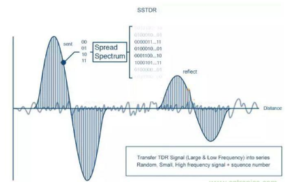
Typical applications in short-range data transceivers are satellite positioning systems (GPS), 3G mobile communications, WLAN (IEEE 802.11a, IEEE 802.11b, IEEE 802.11g) and Bluetooth technology. Spread spectrum technology also helps to improve the utilization of radio frequencies (radio spectrum is limited and therefore an expensive resource).
The basis of spread spectrum theory
The role of spectrum spreading is evident in the Shannon and Hartley channel capacity theorem:
C = B × log2 (1 + S/N) (Formula 1)
Where C is the channel capacity in bits per second (bps), which is the maximum data rate allowed under a theoretically acceptable bit error rate (BER); B is the required channel bandwidth in Hz; S/N is the signal-to-noise power ratio. C represents the amount of information allowed by the communication channel and also represents the desired performance. Bandwidth (B) is the price paid, as frequency is a limited resource. S/N represents the surrounding environment or physical characteristics (such as obstacles, blockages, and interference).
When used in harsh environments (e.g., extremely low signal-to-noise ratio due to noise and interference), it can be seen from the above formula that by increasing the signal bandwidth (B), the communication performance (C) can be maintained or improved, and even the signal power can be lower than the noise floor. (There is no restriction on this condition in the formula!)
Change the logarithmic base in Formula 1 from 2 to e (natural number), expressed as ln = loge, and then:
C/B = (1/ln2) × ln(1 + S/N) = 1.443 × ln(1 + S/N) (Formula 2)
By MacLaurin series expansion we get:
ln(1 + x) = x – x/2 + x/3 – x4/4 + … + (-1)k+1xk/k + …:
C/B = 1.443 × (S/N – 1/2 × (S/N) + 1/3 × (S/N) – …) (Formula 3)
In spread spectrum applications, the signal-to-noise ratio (S/N) is usually low. (As mentioned above, the signal power density can even be lower than the noise floor.) Assuming that the noise is large enough to make S/N << 1, the Shannon expression is approximately:
C/B ≈ 1.433 × S/N (Formula 4)
It can be further simplified as:
C/B ≈ S/N (Formula 5)
or:
N/S ≈ B/C (Formula 6)
To transmit information error-free for a given signal-to-noise ratio in a channel, we only need to perform the basic signal spreading operation: increasing the transmission bandwidth. This principle seems simple and clear, but the specific implementation is very complicated. Because the baseband spread (which may be extended by several orders of magnitude) causes the electronic components to interact, resulting in spreading and despreading operations.
definition
There are many ways to implement spread spectrum technology, but the idea is the same: add an index (also called a code or sequence) to the communication channel. The way the code is inserted defines the spread spectrum technology in question. The term "spread spectrum" refers to expanding the signal bandwidth by several orders of magnitude, and spreading is achieved by adding an index to the channel.
A more precise definition of spread spectrum technology is: a radio frequency communication system that extends the baseband signal to a wider frequency band by injecting a higher frequency signal (Figure 1), that is, the energy of the transmitted signal is spread to a wider frequency band, making it look like noise. The ratio of the extended bandwidth to the initial signal is called processing gain (dB). Typical spread spectrum processing gain can range from 10dB to 60dB.
Spread spectrum technology is used, that is, the corresponding spreading code is simply introduced somewhere in the transmission link before the antenna (this process is called spread spectrum processing), and the information is spread into a wider frequency band. Conversely, removing the spreading code before the data is restored in the receiving link is called despreading. Despreading is to reconstruct the information in the original bandwidth of the signal. Obviously, the spreading code needs to be known in advance at both ends of the information transmission path (in some cases, it should only be known by the two parties transmitting the information).

Bandwidth of spread spectrum processing

Spread spectrum modulation is applied to the front end of a common modulator such as BPSK or direct conversion. Signals that do not receive a spreading code remain unchanged and are not spread.
Despreading bandwidth
Similarly, the despreading process is shown in Figure 3:

Despreading is usually performed before demodulation. Signals added during transmission (such as interference or blockage) will be spread in the despreading process.
The bandwidth wasted due to spread spectrum is compensated by multiple users
The direct result of spectrum spreading is to occupy a wider frequency band (the spreading factor is related to the "processing gain" mentioned above), thus wasting limited frequency resources. However, the occupied frequency band can be compensated by multiple users sharing the same extended frequency band (Figure 4).
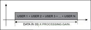
Spread spectrum is a broadband technology
The spread spectrum process is a wideband technology compared to narrowband technology. For example, W-CDMA and UMTS are wideband technologies that require a wider frequency band (compared to narrowband radio).
Benefits of Spread Spectrum
Anti-interference and anti-blocking performance
Spread spectrum technology brings many benefits, and anti-interference is the most important advantage. Because the interference and blocking signals do not carry the spreading factor, they are suppressed. After despreading, only the desired signal containing the spreading factor will appear in the receiver. See Figure 5.
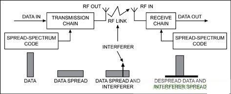
If the interfering signal (narrowband or broadband) does not include the spreading factor, its effect can be ignored after despreading. This suppression capability also works on other spread spectrum signals that do not have the correct spreading factor. It is precisely because of this that spread spectrum communication allows different users to share the same frequency band (such as CDMA). Note that spread spectrum is a broadband technology, but broadband technology is not spread spectrum, and broadband technology does not necessarily include spread spectrum technology.
Prevent signal interception
Protection from signal interception is the second advantage gained through spread spectrum. Because unauthorized users do not know the spreading factor that spreads the original signal, they cannot decode it. Without the correct spreading factor, the spread signal is equivalent to noise or interference (of course, if the spreading factor is very short, it can be cracked using scanning methods). Fortunately, spread spectrum communication allows the signal power to be below the noise floor because the spreading process reduces the spectral density, see Figure 6 (total energy is the same but spread across the entire frequency domain). In this way, the information can be hidden, an effect that is the prominent feature of Direct Sequence Spread Spectrum (DSSS) (DSSS will be described in detail later). Other receivers cannot resolve this transmission, and the only impact on them is a slight increase in total noise power!

Fading suppression (multipath effects)
Wireless channels often have multipath propagation effects, where there is more than one path from the transmitter to the receiver (Figure 7). These paths are caused by reflection or refraction in the air and reflection from the ground or objects such as buildings.

The interference of the reflected path (R) on the direct path (D) is called fading. Since the despreading process is synchronized with the signal D, even if the signal R contains the same spreading factor, it will be suppressed. The signal of the reflected path can be despread and its RMS value added to the main signal.
Application of Spread Spectrum Technology in CDMA
It is worth noting that spread spectrum is not a modulation method and should not be confused with other types of modulation. For example, we can use spread spectrum technology to transmit a signal modulated by FSK or BPSK. From the basic theory of coding, spread spectrum can also be used as a method to achieve multiple access communication (multiple communication links coexist on the same physical medium at the same time). So far, there are three main methods.
FDMA—Frequency Division Multiple Access
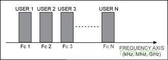
FDMA assigns a specific carrier frequency to each communication channel, and the number of users is limited by the number of frequency bands in the spectrum (Figure 8). Among the three multiple access implementation methods, FDMA has the lowest frequency band utilization. Typical applications include wireless broadcasting, TV, AMPS, and TETRAPOLE.
TDMA—Time Division Multiple Access
In TDMA, the communication between different users is based on the allocated time slots (Figure 9). In this way, different communication channels can be established on one carrier frequency. TDMA is used in GSM, DECT, TETRA and IS-136.

CDMA—Code Division Multiple Access
CDMA spatial access depends on the spreading factor or code (Figure 10). In a sense, spread spectrum is a method of CDMA. The transmitter and receiver need to know the defined spreading code in advance. Typical applications include IS-95 (DS), IS-98, Bluetooth technology and WLAN.
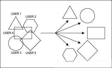
In practical applications, the above multiple access methods can be used in combination. For example, GSM combines TDMA and FDMA, defines topological areas (cells) using different carrier frequencies, and sets time slots in each cell.
Spreading and Codec Factor
The main feature of spread spectrum is that the transmitter and receiver must know a preset spread spectrum code or spread spectrum factor in advance. In modern communications, spread spectrum codes must be long enough and as close to a random number sequence similar to noise as possible. However, in any case, they must remain recoverable. Otherwise, the receiver will not be able to extract the transmitted information. Therefore, this sequence is approximately random. Spread spectrum codes are usually called pseudo-random codes (PRN) or pseudo-random sequences. Pseudo-random codes are usually generated using feedback shift registers.
Figure 11 shows an example of a pseudo-random code. The shift register contains 8 data flip-flops (FFs), and the content in the shift register is shifted left bit by bit on the rising edge of the clock. The data shifted into FF1 depends on the feedback information of FF8 and FF7. The pseudo-random code PRN is read out from FF8. The content of the flip-flop is reset at the beginning of each sequence.
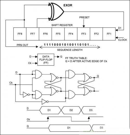
Many books have been written on the generation and characteristics of PRNs, but these basic guidelines have not kept pace with the pace of development. The generation or selection of an appropriate sequence (or set of sequences) is not straightforward. To ensure effective spread spectrum communication, the PRN sequence must consider several criteria, such as length, autocorrelation, cross-correlation, orthogonality, and bit equalization. The more commonly used PRN sequences are: Barker, M-Sequence, Gold, and Hadamard–Walsh. The more complex the sequence set used by the spread spectrum communication link, the higher its reliability. However, the price paid is that the electronics required for the despreading operation will also be more complex (both in terms of speed and performance). Digital despreading chips can contain millions of equivalent 2-input NAND gates, switching at tens of megahertz.
Different modulation methods of spread spectrum technology
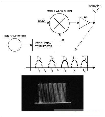
Different spread spectrum modulation methods can be obtained according to the position of the pseudo random code (PRN) inserted into the communication channel. Figure 12 is a basic RF front-end principle description.
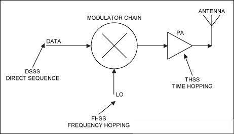
If a pseudo-random sequence code is added directly to the data, direct sequence spread spectrum (DSSS) can be obtained (in actual applications, the pseudo-random sequence is multiplied with the communication signal to produce data that is completely "disrupted" by the pseudo-random code). If the pseudo-random code acts on the carrier frequency, we get frequency hopping spread spectrum (FHSS). If the pseudo-random code acts on the local oscillator, the FHSS pseudo-random code forces the carrier to change or jump according to the pseudo-random sequence. If the pseudo-random sequence is used to control the on or off of the transmitted signal, time hopping spread spectrum technology (THSS) can be obtained. This is also a linear frequency modulation pulse technology, that is, the carrier frequency is linearly scanned within one cycle. The above technologies can also be combined to form a hybrid spread spectrum technology, such as DSSS + FHSS. DSSS and FHSS are the two most commonly used technologies now.
Direct Sequence Spread Spectrum (DSSS)
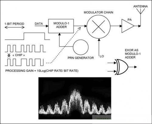
In direct sequence spread spectrum technology, a pseudo-random code is added directly to the data of the carrier modulator. Therefore, the modulator appears to have a higher code rate, which is related to the chip rate of the pseudo-random sequence. The result of modulating the RF carrier with such a code sequence is a direct sequence modulated spread spectrum centered at the carrier frequency with a spectrum of ((sin x)/x).
The bandwidth of the main lobe (zero to zero) of the spectrum is twice the modulation code clock rate, and the side lobe bandwidth is equal to the modulation code clock rate. Figure 13 is a typical example of a direct sequence spread spectrum signal. Some changes in the shape of the direct sequence spread spectrum spectrum are related to the actual carrier and data modulation method used. The following is a binary phase shift keying (BPSK) signal, which is a common modulation type used in direct sequence spread spectrum systems.
Frequency Hopping Spread Spectrum (FHSS)
As the name implies, in FHSS the carrier frequency jumps from one frequency to another over a wide frequency band as defined by a pseudo-random code. The hopping rate is determined by the data rate of the original information, and we can identify fast frequency hopping (FFHSS) and slow frequency hopping (LFHSS). The latter (most common) allows several consecutive data bits to modulate the same frequency, while FFHSS is multiple frequency hopping within each digital bit.
The transmission spectrum of the frequency hopping signal is very different from that of the direct sequence spread spectrum. The frequency hopping output is flat across the entire frequency band (as shown in Figure 14), rather than a ((sin x)/x) envelope. The bandwidth of the frequency hopping signal is N times the frequency gap, where N is the bandwidth of each hopping channel.
Time Hopping Spread Spectrum (THSS)
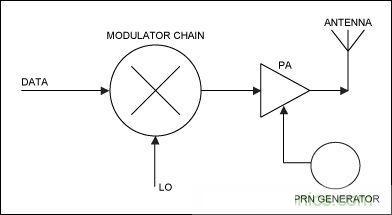
Figure 15 shows the time-hopping spread spectrum technology. This technology has not made any major breakthroughs so far. It uses a pseudo-random sequence to control the on/off of the PA.
System Implementation and Conclusion
A complete spread spectrum communication link requires the use of various advanced technologies and processes: RF antenna, high-power, high-efficiency power amplifier, low-noise, high-linearity LNA, highly integrated transceiver, high-resolution ADC and DAC, high-speed, low-power digital signal processor (DSP), etc. Designers and manufacturers compete with each other and cooperate sincerely, which ultimately makes the spread spectrum system possible.
The most difficult circuit to implement is the receiving channel, especially the despreading of DSSS, because the receiving end must be able to recover the original information and synchronize in real time. Code recognition is also called correlation operation, which is implemented in the digital domain and requires fast and large-scale binary addition and multiplication operations.
By far, the most complex problem in receiver design is synchronization. Compared with other technologies in spread spectrum communication, the development of synchronization technology has taken more time, money, manpower and material resources. Currently, there are many ways to solve the synchronization problem, and most solutions require a large number of discrete components. The emergence of DSP and application-specific integrated circuits (ASICs) has brought a major breakthrough. DSP provides high-speed mathematical computing capabilities, and performs analysis, synchronization and decorrelation operations after dividing the spread spectrum signal. With the help of very large-scale integrated circuit (VLSI) technology, ASIC reduces system costs and makes it suitable for a variety of applications by creating a basic module architecture.
| 


 提升卡
提升卡 变色卡
变色卡 千斤顶
千斤顶
