To participate in this Lichuang EDA & Tuya Smart Practical Training Camp, you are required to do IoT-related work using Tuya’s cloud modules. When I mention the cloud, the first thing that comes to my mind is smart home. In my spare time, I also do a lot of projects related to the Internet of Things, large and small. Almost all the electrical appliances at home have been converted into smart ones. I happened to have the idea of making an infrared remote control air conditioner recently, and due to work reasons, there is a need for Tuya smart cloud development, so I participated in this training camp.
Winter is coming. I wake up too early in the morning and dare not lift the quilt (too cold/laughing and crying). I have always wanted to change it to a smart one, which can be controlled with a mobile phone, supports scheduled on/off, and supports intelligent scene linkage.
To realize air conditioning control, it is necessary to send infrared, so it must have infrared sending function. There are many types of air conditioners on the market, and they must be suitable for multiple brands and models, so they must have infrared learning functions. To support scene linkage, environment sensing sensors are needed. To support mobile phone control, cloud and modules are required.
In summary, the design functions are:
1. Infrared transmission (infrared transmitting tube); 2. Infrared learning (integrated receiving head); 3. Indoor temperature detection (DHT11); 4. Mobile phone control (Tuya module).
In actual scenarios, the installation position of air conditioners is generally not fixed, so the infrared controller cannot control it at close range. Refer to the design of infrared controllers of other major brands and adopt a wall-mounted design. Can be hung on the ceiling or wall.
The control board was all drawn with Lichuang EDA and patched by hand. The text on the graffiti module was washed away by the cleaning agent, and the operation was careless (/face covering).

The male mold shell used and the installation effect.


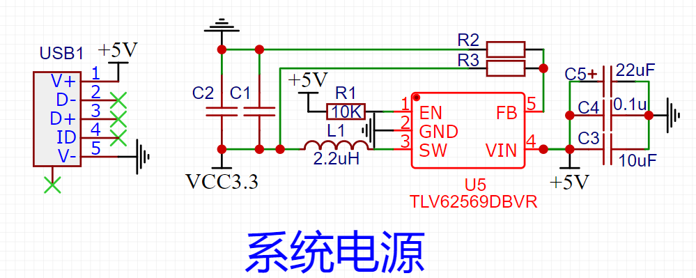
The power supply part uses a Micro USB interface to directly provide 5V power. After internal voltage division, a 3.3V voltage is obtained to power the MCU, Tuya modules and peripheral circuits. The voltage reduction uses TI's TLV62569DBVR power chip, which has fewer peripheral components, high power and small ripple.
The WBR1D-IPEX module provided by Tuya Smart is used. WBR1D is a dual-band dual-mode module that supports WIFI and Bluetooth and adopts an MCU access solution. Connect to MCU through serial port.

The MCU uses ST's STM32F103C8T6 and 64K Flash.
Infrared emission uses infrared tubes. Since it is a wall-mounted installation, the control range is required. In this design, 8 infrared emission tubes are connected in parallel. Each tube is driven by a high-power triode, and all triodes are driven by a control terminal. To increase the transmission power, after increasing the transmission power, the infrared control range will be significantly expanded. (Multiple infrared tubes are best controlled in parallel. Do not choose to connect them in series for the convenience of drawing PCB or to save components. The tubes connected in series will not work properly and the transmission power will be greatly reduced.)

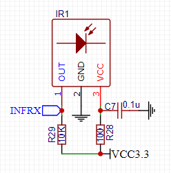
Infrared reception is relatively simple, directly using an integrated receiving head.
The button is used for network configuration, but during actual debugging, the module will automatically configure the network, so the button is changed to clear the infrared pre-stored data.
The LED is used only for distribution network status and indication of entering infrared learning mode, as well as fault flashing.
DHT11 is used to detect indoor temperature and humidity. In this design, the infrared remote control is used as a single product. DHT11 can report indoor temperature and humidity to the cloud, enabling intelligent scene linkage.
When designing the PCB, because it was wall-mounted, I chose a male mold housing, purchase link . During design, the device layout and PCB shape must conform to the housing size.
shell:

PCB: The first version of the PCB has several errors. The button position and the LED position are reversed, and the silk screen printing is wrong. It has been updated.

Infrared reception is relatively simple. If it is an NEC format code that is easy to parse, just use a timer to capture the length of the external input level. For codes that are difficult to parse (manufacturer-defined codes), use external interrupts and timers to measure the level. length of time. For NEC format encoding, according to the specifications of the NEC encoding format, the low-level time is first determined, and the start code, data code and end code are distinguished by length. There are many routines on the Internet, so I won’t go into details here. It should be noted that although some manufacturers’ air conditioners use NEC encoding, the high and low level lengths in their encoding are generally different, so when judging the level length in an interrupt, you must Pay attention to the setting range.
For specific implementation code, please refer to the program in the attachment.
Infrared emission is completed by the infrared tube. Note: if the infrared tube does not emit infrared, the output at the receiving end is 1, and if the infrared tube is emitting infrared, the output at the receiving end is 0. Pay attention to the distinction here.
The implementation method is to use a timer to output a 38K square wave, and control the length of the square wave output to send different data and codes. This project uses two timers to transmit infrared. TIM1 outputs 38K carrier wave, and TIM3 is timed by TIM3 to control TIM1 output/turn off PWM, so that transmission of any length of time can be achieved. However, this consumes MCU resources. For STM32, it has little impact. For small MCUs, resources must be considered.
The following is the key code to implement infrared transmission:
Send a complete set of infrared encoding Inf_RX_NECcoding()
void Inf_RX_NECcoding(uint8_t *pbuff,uint8_t Length,uint8_t quantity)
{
    uint8_t i;
    TIM_CtrlPWMOutputs(TIM1,ENABLE);  //开输出
    TIM_Cmd(TIM3,ENABLE);  //开定时器
    TIM_Cmd(TIM1,ENABLE);

  while(Inf_RX_StartCode()); //起始码

    if(Length>InfraredDataLength)  //数据有效长度限制
        Length = InfraredDataLength;

    for(i=0;iInfraredDataLength)
        Length = InfraredDataLength;

    for(i=0;i数据发送(1个8位)

``` cpp
uint8\_t Inf\_RX\_StartCode(void)
 {
  if(!retemp)
  {
  retemp=1;
  TimerOclk=0;
  TIM_SetCompare1(TIM1,1100); //设置占空比为50%
  }
  if(TimerOclk==441) //低电平时间到
  TIM_SetCompare1(TIM1,0); //设置占空比为0
  if(TimerOclk==881) //高电平时间到
  {
  retemp=0;
  TimerOclk=0;
  }
  return retemp; //状态返回
 }
Space is limited, please refer to the attachment for the rest of the code.
In this project, only NEC coded infrared learning is implemented. When pressing the control on the mobile phone, if there is no instruction, it will automatically enter the learning state and wait for the infrared instruction to be sent. After the infrared command is received, it will be automatically saved.
Because Tuya’s MCU access solution is used, the cloud only configures functions and APP interfaces, downloads the MCU SDK, and transplants the SDK into the code.
Cloud function configuration

APP interface configuration

During the actual test, we encountered problems such as equipment disconnection and unresponsive control. At first, we thought it was a network problem. After changing the network, the problem still existed. After removing the board, I found that the entire PCB was hot. When I measured the power supply to the MCU, it was only close to 2V. It is said that it can work normally. Unplug the power supply and plug it in again, and the MCU power supply will be restored. While waiting for the problem to reoccur, it was measured that the control end of the infrared tube drive triode was always at a low level. The problem was discovered: the emission power of the 8 infrared emission tubes was relatively large, and the output might be interrupted when the output was turned off, causing the shutdown to fail. Successfully, the infrared tube has been in the sending state. As time goes by, the total current of the 8 infrared tubes increases, and the current provided to the MCU decreases, causing a suspended animation phenomenon.
In order to solve this problem, three lines of defense have been added. One is to turn off the output and timer together after each transmission is completed, which can reduce the chance of interrupt conflicts. The second is to add STM32 internal temperature measurement. Once the temperature is detected to exceed the allowable value, the timer and PWM output will be controlled once. If the alarm value is exceeded, the MCU will be reset directly. The third is to add a watchdog and feed the dog regularly to prevent suspended animation and program runaway.
After adding these three lines of defense, the actual measurement problem no longer occurs. For specific implementation code, please refer to the attachment.
Tuya provides a matching MCU SDK. Tuya also provides a lot of documentation on specific usage methods. There are also many cases on site b. We only need to transplant it into the MCU and realize MCU access through serial communication. Pay attention to the baud rate of the serial port connected to the Tuya module. The default is generally 9600, but it can also be modified to 115200. Specifically, modify it in the hardware development -> module firmware of the cloud console. There are a few things to pay attention to when transplanting:
mcu_api.c
1. The serial port receiving function uart_receive_input() must use the interrupt method to receive data to prevent data packet loss.
Tuya provides serial port data reception buffering and data processing methods. We no longer need to do the processing separately. We only need to call the uart_receive_input() function in the serial port reception interrupt.
//USART2中断服务函数
 void USART2_IRQHandler(void)
 {
   uint8_t value ;
   if(USART\_GetITStatus(USART2, USART\_IT\_RXNE) != RESET)  //接收中断
  {
    value = USART_ReceiveData(USART2); //读取接收数据
  uart\_receive\_input(value); //数据存入涂鸦缓冲器
  }
 }
2. Data polling function wifi_uart_service(), this function must be polled, otherwise the MCU cannot receive the data sent by the module. Just put it in the main loop.
while (1)
 {
     wifi\_uart\_service(); //轮询涂鸦数据
     /*
       用户其他函数
     */
 }
3. The protocol initialization function wifi_protocol_init() provides a cache space for Tuya serial port data. It is called during initialization and does not need to be called again after initialization.
int main(void)
 {
  wifi\_protocol\_init(); //涂鸦模组协议初始化
     /*
       用户其他初始化函数
     */*
*     while(1)*
*    {*
*        wifi\_uart\_service(); //轮询涂鸦数据*
*     /*
       用户其他函数
     */
    }
 }
protocl.c
1. The serial port sending function uart_transmit_output() can be sent by calling method or interrupt.
Tuya provides a serial port sending data processing method. We don’t need to do the processing separately. We only need to put the serial port sending statement in the uart_transmit_output() function.
void uart\_transmit\_output(unsigned char value)
 {
   while((USART2->SR &(1<<7))==0);
  USART2->DR = value;
 }
2. All data reporting function all_data_update()
We need to pass in the device data in the all_data_update function. The Tuya module may apply to the MCU to return all the data of the device. The device data is sent through the all_data_update function, so the data items of the device must be passed into the corresponding function. Note: This function corresponds to the function defined by your own cloud and cannot be added directly.
void all\_data\_update(void)
 {
     //此代码为平台自动生成,请按照实际数据修改每个可下发可上报函数和只上报函数
     mcu\_dp\_bool\_update(DPID\_SWITCH,AirControlStructure.AirPowerControl); //BOOL型数据上报; //当前开关
     mcu\_dp\_value\_update(DPID\_TEMP\_SET,AirControlStructure.AirRunTemper); //VALUE型数据上报; //当前温度设置
 // mcu\_dp\_value\_update(DPID\_TEMP\_CURRENT,AirControlStructure.AirRunTemper); //VALUE型数据上报; //当前当前温度
     mcu\_dp\_enum\_update(DPID\_MODE,AirControlStructure.AirRunMode); //枚举型数据上报; //当前工作模式
     mcu\_dp\_enum\_update(DPID\_FAN\_SPEED\_ENUM,AirControlStructure.AirRunFan); //枚举型数据上报; //当前风速
 //   mcu\_dp\_enum\_update(DPID\_STATUS,AirControlStructure.AirRunFlag); //枚举型数据上报; //当前状态
     mcu\_dp\_bool\_update(DPID\_AUTO,AirControlStructure.AirForceful); //BOOL型数据上报; //当前自动模式
     mcu\_dp\_bool\_update(DPID\_HEAT,AirControlStructure.AirHeat); //BOOL型数据上报; //当前辅热
 }
3. A single data delivery processing function. Tuya defines the processing function corresponding to the function in protocl.c. We need to implement the control code in the corresponding function. Example
static unsigned char dp\_download\_switch\_handle(const unsigned char value[], unsigned short length)    //开关
 {
     //示例:当前DP类型为BOOL
     unsigned char ret;
     //0:关/1:开
     unsigned char switch_1;

switch\_1 = mcu\_get\_dp\_download\_bool(value,length);
     if(switch_1 == 0) {
  AirControlStructure.AirPowerControl=OFF;//关
  AirControlStructure.AirHeat = OFF;       //辅热关
     AirControlStructure.AirForceful = OFF;   //强劲关
    }else {
  AirControlStructure.AirPowerControl=ON; //开
    }
  AirControlInfRX(); //发送红外代码

//处理完DP数据后应有反馈
     ret = mcu\_dp\_bool\_update(DPID\_SWITCH,switch\_1);
     if(ret == SUCCESS)
         return SUCCESS;
     else
         return ERROR;
 }
In fact, the MCU access solution is serial communication. Tuya provides an SDK. Define the functions in the cloud, configure the firmware and APP panel, download the SDK package, transplant it to the MCU code and use it. There is no need to do tedious processes such as setting up the function, network configuration, and cloud migration separately. This is very friendly to product developers, whether it is testing or research and development.
After the above work is completed, the key point comes. No matter how beautifully the code is written and the circuit design is perfect, it is still equal to 0 if the air conditioner cannot be controlled. Everyone knows that the air conditioner is controlled by an infrared remote control, so this project is to transmit the infrared code emitted by the air conditioner remote control to control the air conditioner instead of the remote control. The difficulty here is how to obtain the infrared code of the air conditioner. The infrared codes of air conditioners currently on the market are all customized by the manufacturers. The specific encoding protocol will not be provided in the after-sales service or in the manual, so you can only analyze it yourself. The parsing process is briefly described below. The parsing process is cumbersome and the document is lengthy. For details, please go to Yuque Documents Air Conditioning Remote Control Code Analysis
First, we need to obtain the infrared encoding. My method is to use a logic analyzer and an infrared receiver, press a button on the remote control, view the waveform captured by the analyzer, and parse the data through the waveform. This process is not difficult, but it is very tedious.

Taking power on as an example, press the power button, the remote control sends a set of infrared codes, and the logic analyzer captures the waveform, as shown in the figure

Press the power button repeatedly. The waveform captured by the analyzer is the same every time. The waveform is enlarged and printed, as shown in the figure:

This is a complete set of infrared waveforms. I only need to send the same code as this set of waveforms to control the air conditioner to turn on. But now we only know the level conversion time, but we don’t know what the specific conversion time represents. However, it can be seen from this complete set of waveforms that it complies with the NEC encoding format (if you don’t understand the NEC infrared encoding format, please check the relevant information first), but the level conversion time length is slightly different, so try using NEC first. Try the encoding receiving program. Through the NEC coded infrared receiving program test, it was found that the data can be received:

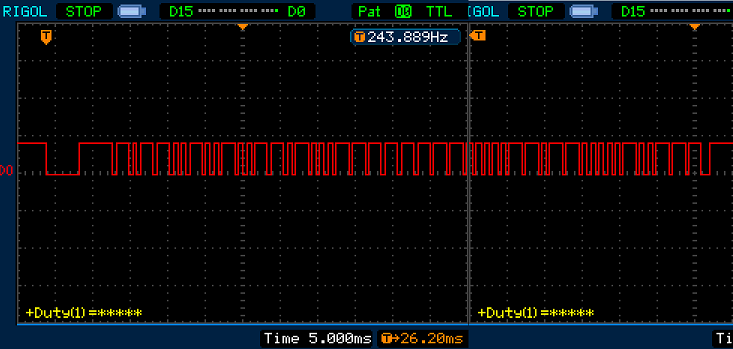
So now by directly sending this set of infrared data, you can control the air conditioner to turn on. However, there is no way to control it in the actual test, and the air conditioner does not respond. In turn, look at the waveform captured by the logic analyzer. This waveform is different from the standard NEC encoded transmit waveform except for the high and low level conversion time length and the total length. Take a closer look at this boot waveform. The first half and the second half are the same. The front and back half of the waveform are intercepted according to the NEC format.
first half:
Second half:
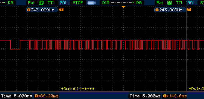
I was surprised to find that their start code and data code are the same, and the end code is slightly different. It can be seen that this infrared encoding is composed of two frames. There is an intermediate code between the two frames, which is the connection and the first code. frame and the second frame. Combine the first frame waveform, the second frame waveform and the complete waveform to obtain the intermediate code waveform.

Through the logic analyzer, the intermediate level change time relationship is:
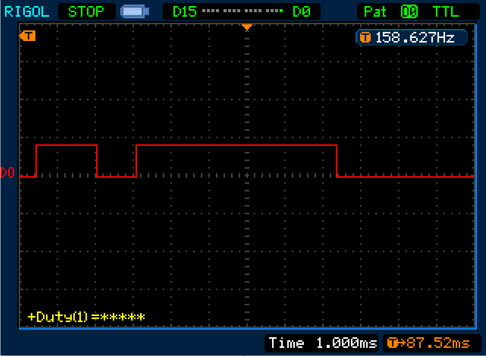

From this, the level change time intervals of the start code, data code, intermediate code and end code are analyzed, and the infrared transmission function is redefined according to the analysis results, and the test can be started normally.
In addition to the default functions, the APP interface has added some functions. Because the public version of the APP interface is used, the scope of interface UI and function customization is limited. It will be changed to panel SDK development in the future. At this stage, there is not much time and development cannot be done.
Take powerful functions as an example. During the design of this project, no powerful functions were added. To add now, first enter the Tuya IoT platform, find the project, enter the APP panel configuration page, and click "Edit" on the page.
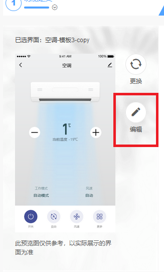
Enter the editing page, first select the location to add the button, add it to more pages here

After configuring the properties and associated functions, click Publish and Tuya will automatically package it. After packaging, a test QR code will be provided. Scan the QR code to test this panel. If the test passes, it will be officially released. After the release, the mobile phone will exit. If you re-enter the "Tuya Smart" APP, the added functions will take effect.

All reference designs on this site are sourced from major semiconductor manufacturers or collected online for learning and research. The copyright belongs to the semiconductor manufacturer or the original author. If you believe that the reference design of this site infringes upon your relevant rights and interests, please send us a rights notice. As a neutral platform service provider, we will take measures to delete the relevant content in accordance with relevant laws after receiving the relevant notice from the rights holder. Please send relevant notifications to email: bbs_service@eeworld.com.cn.
It is your responsibility to test the circuit yourself and determine its suitability for you. EEWorld will not be liable for direct, indirect, special, incidental, consequential or punitive damages arising from any cause or anything connected to any reference design used.
Supported by EEWorld Datasheet