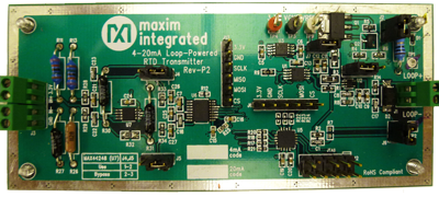
 HD pictures |
4–20mA current loops are widely used as analog communication interfaces in industrial applications to send data from remote sensors over twisted pair cables to a programmable logic controller (PLC) in a central control center . In the design, 4mA represents the lowest temperature value, and 20mA represents the highest measurement temperature. The main advantages of the current loop are fourfold: first, the signal accuracy is not affected by the voltage drop in the loop, as long as the supply voltage is higher than the total voltage drop of the loop; second, using two wires as the power supply and the entire Loop data communication; third, better noise immunity; finally, low cost and simple installation.
The Monterey design is based on a complete Maxim solution and combines ultra-low power consumption with high accuracy and precision.
Loop-powered sensor transmitters are targeted at industrial sensors, industrial automation, and process control, but can be used in any application that requires high-precision conversion.
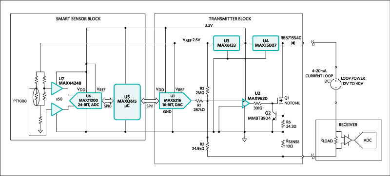
Simplicity, reliability, good noise immunity, long range, and low cost make the Monterey (MAXREFDES15#) ( Figure 1 ) interface ideal for industrial process control and remote object automation.

High-definition picture (GIF)
Figure 1. Monterey subsystem design block diagram
Ultra low power consumption
-100°C to +100°C range
High accuracy
High precision
Simple power supply and wide input range
System current consumption is less than 2.1mA
Resistance Temperature Detector (RTD) PT1000
Resolution is 10,000 words or 0.1%
Accuracy is 0.25%
10V to 40V power supply
High precision ammeter
RTD PT1000 sensor or temperature calibrator
C connect the industry standard power supply to the LOOP+ and LOOP- ends of J1 to power the circuit board.
Connect the sensor to J3. The current design configuration of the board is for a 2-wire RTD application. With minor modifications to the sensor side, it can be used in 3/4-wire RTD applications.

All reference designs on this site are sourced from major semiconductor manufacturers or collected online for learning and research. The copyright belongs to the semiconductor manufacturer or the original author. If you believe that the reference design of this site infringes upon your relevant rights and interests, please send us a rights notice. As a neutral platform service provider, we will take measures to delete the relevant content in accordance with relevant laws after receiving the relevant notice from the rights holder. Please send relevant notifications to email: bbs_service@eeworld.com.cn.
It is your responsibility to test the circuit yourself and determine its suitability for you. EEWorld will not be liable for direct, indirect, special, incidental, consequential or punitive damages arising from any cause or anything connected to any reference design used.
Supported by EEWorld Datasheet