This case is a configuration case of using the MODBUS to PROFINET gateway of Bestun Technology to connect the Senlan inverter and PLC. The devices used are Siemens S7-1200PLC, MODBUS RTU to PROFINET gateway, and Senlan inverter.

1. First create a new project file;

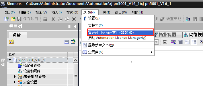
2. Import the GSD file. Copy the GSD file of the MODBUS to PROFINET gateway to any location. Open Portal and create a new project. Enter Devices and Networks, select Manage General Station Description Files in the Options, and install the GSD file;

3. Search for the folder where the GSD file is stored. After finding the GSD, select Install and wait for the installation to succeed.

4. After successfully installing GSD, open the hardware directory and add the installed GSD file to the configuration. The MODBUS to PROFINET gateway and PLC have not yet been connected and are in an unassigned state;

5. Click Unassigned to connect to the PLC and then set the parameters of the MODBUS to PROFINET gateway properties;

6. Modify the properties of the MODBUS to PROFINET gateway, modify the IP address and PROFINET device name of the MODBUS to PROFINET gateway (do not include symbols such as *./ in the device name);

7. Add the required input (inptu) and output (output) bytes. Add the bytes as required;

8. After setting the parameters, you can download and load it to the PLC as shown in the figure below;

9. Open the configuration software Gateway Configuration Studio;

10. Click New and select the device as PN2MRM3;

11. The IP address in the configuration software must be consistent with the IP address in the Botu MODBUS to PROFINET gateway configuration;

12. The PROFINET configuration in the configuration software must be consistent with the PROFINET gateway configuration of Botu MODBUS;

13. Configure the baud rate, word width (data bit selection), parity check and other parameters according to the device instructions. From the figure, we can see that the inverter slave protocol is Modbus-Rtu communication data format with 8 data bits and one stop bit without check. Similarly, the gateway is configured in the same way;

14. Take the device description in the figure below as an example. In the device description, address 1, function code 3/10, the address to be written is 3200H, 3201H. The configuration of writing the main control word is as follows;


15. After configuring all the required parameters, download, click Tools and then click Communication Settings;


16, the hexadecimal address is converted to the decimal starting address. Write 12800 register quantity. Two representatives can input the main control word start and stop and the given frequency. Read using the 03 function code. If you want to read the value from the main status word to the FF-17 process word to select the output, then you need to fill in 10 register data starting from 12816. Click Search to enter the next interface and then click Search and double-click the IP and device in the red box below.
Previous article:SIMATIC S7-1500 PLC multiple background applications 1-2
Next article:ETHERNET IP to ETHERCAT connection ethercat bus servo how to control
- Popular Resources
- Popular amplifiers
- Detailed explanation of intelligent car body perception system
- How to solve the problem that the servo drive is not enabled
- Why does the servo drive not power on?
- What point should I connect to when the servo is turned on?
- How to turn on the internal enable of Panasonic servo drive?
- What is the rigidity setting of Panasonic servo drive?
- How to change the inertia ratio of Panasonic servo drive
- What is the inertia ratio of the servo motor?
- Is it better for the motor to have a large or small moment of inertia?
 Professor at Beihang University, dedicated to promoting microcontrollers and embedded systems for over 20 years.
- LED chemical incompatibility test to see which chemicals LEDs can be used with
- Application of ARM9 hardware coprocessor on WinCE embedded motherboard
- What are the key points for selecting rotor flowmeter?
- LM317 high power charger circuit
- A brief analysis of Embest's application and development of embedded medical devices
- Single-phase RC protection circuit
- stm32 PVD programmable voltage monitor
- Introduction and measurement of edge trigger and level trigger of 51 single chip microcomputer
- Improved design of Linux system software shell protection technology
- What to do if the ABB robot protection device stops
- Melexis launches ultra-low power automotive contactless micro-power switch chip
- Melexis launches ultra-low power automotive contactless micro-power switch chip
- Molex leverages SAP solutions to drive smart supply chain collaboration
- Pickering Launches New Future-Proof PXIe Single-Slot Controller for High-Performance Test and Measurement Applications
- Apple faces class action lawsuit from 40 million UK iCloud users, faces $27.6 billion in claims
- Apple faces class action lawsuit from 40 million UK iCloud users, faces $27.6 billion in claims
- The US asked TSMC to restrict the export of high-end chips, and the Ministry of Commerce responded
- The US asked TSMC to restrict the export of high-end chips, and the Ministry of Commerce responded
- ASML predicts that its revenue in 2030 will exceed 457 billion yuan! Gross profit margin 56-60%
- Detailed explanation of intelligent car body perception system
- Which company can make PCB boards with a width of about 2MM?
- How to speed up the program running speed of Huada HC32F460 HC32F4A0?
- FPDLINK Spark Interference Optimization
- Why do electrolytic capacitors explode? Find out in one article!
- Namisoft's design report on labview spectrum analyzer
- [Iprober 520 current probe] Calibration and use in PCB mode
- A brief history of hard disk interface evolution
- Hot plug and unplug
- EEWORLD University ---- STM32CubeMX and STM32Cube HAL basics
- How to use ATA-L series underwater acoustic power amplifier?

 MCP6V08T-E/MNY


 京公网安备 11010802033920号