1. Characteristics of ladder diagram of PLC control system
(1) Input signal and output load of PLC control system
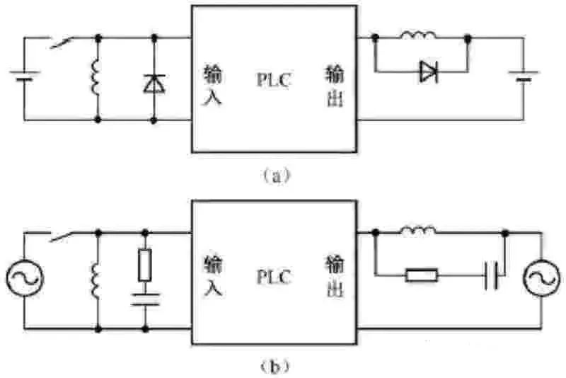
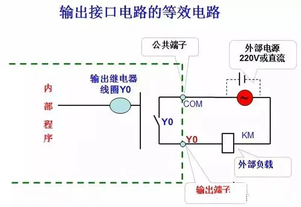
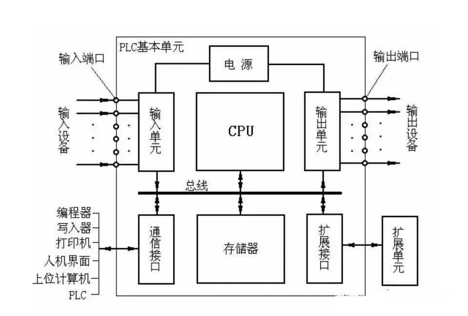
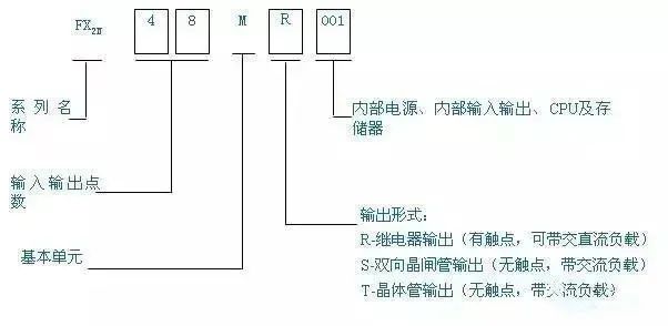
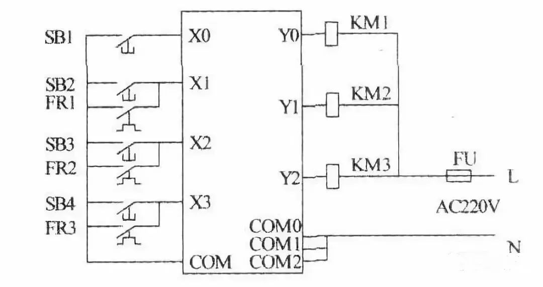
The AC contactors and solenoid valves in the relay circuit diagram are controlled by the output relays of the PLC, and their coils are connected to the output terminals of the PLC. Buttons, control switches, limit switches, proximity switches, etc. are used to provide control commands and feedback signals to the PLC, and their contacts are connected to the input terminals of the PLC.
(2) Treatment of intermediate relays and time relays in relay circuit diagrams
The functions of the intermediate relay and time relay in the relay circuit diagram are completed by the auxiliary relays and timers inside the PLC, and they are not related to the input relays and output relays of the PLC.
(3) Setting up the intermediate unit
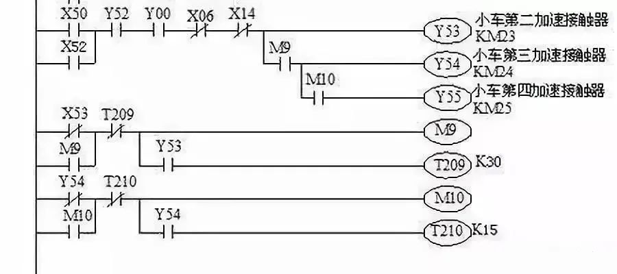
In the ladder diagram, if multiple coils are controlled by a certain contact series/parallel circuit, in order to simplify the circuit, an auxiliary relay controlled by the circuit can be set in the ladder diagram. The auxiliary relay is similar to the intermediate relay in the relay circuit.
(4) Treatment of instantaneous contacts of time relay
In addition to the contacts for delayed action, the time relay also has instantaneous contacts that act immediately when the coil is energized or de-energized. For a time relay with instantaneous contacts, an auxiliary relay can be connected in parallel at both ends of the coil of the corresponding timer in the ladder diagram, and the latter's contacts are equivalent to the instantaneous contacts of the time relay.
(5) Establishment of external interlocking circuit
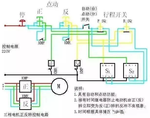
In order to prevent the two contactors controlling forward/reverse rotation from operating at the same time and causing a short circuit in the three-phase power supply, in addition to setting up a soft interlocking circuit consisting of move-break contacts connected in series with the coils of their corresponding output relays in the ladder diagram, a hard interlocking circuit should also be set up outside the PLC.
2. Structural analysis of ladder diagram
Use general programming method or sequential function chart programming method; use single sequence structure of sequential function chart or select sequence structure, parallel sequence structure; use start/hold/stop circuit, step sequence control instruction for programming or set/reset instruction for programming.
The decomposition of the ladder diagram starts with operating the main command circuit (such as a button), and tracing the line to the action of the main circuit control device (such as a contactor). In the middle, it has to pass through many programming components and circuits, which makes it difficult to find.
No matter how complex the ladder diagram is, it is composed of some basic units. According to the composition of the main circuit, the ladder diagram and instruction statement table are decomposed into several basic units corresponding to the electrical appliances (such as motors) of the main circuit using the reverse reading and tracing method, and then analyzed one link at a time, and finally the links are connected using the forward reading and tracing method.
(1) Configuration and function of buttons, travel switches, and transfer switches
There are many travel switches and transfer switches, as well as pressure relays, temperature relays, etc. in the PLC I/O wiring diagram. These electrical components do not have an attraction coil, and the movement of their contacts is achieved by external force or other factors. Therefore, the external force or factors that cause the movement of these contacts must be found first. The travel switch is pressed or released by a mechanical linkage mechanism, and the transfer switch is generally operated manually, so that the contacts of these travel switches and transfer switches are in different working states during the operation of the equipment, that is, the closing and opening of the contacts are different to meet different control requirements. This is a key in the process of reading the diagram.
It is difficult to understand the different working states of the contacts of these travel switches and transfer switches by simply looking at the circuit diagram. It is necessary to combine the equipment manual and the electrical component list to clarify the purpose of the travel switch and transfer switch, the mechanical linkage mechanism of the travel switch, and the working state of the circuit when the contacts are in different closed or open states.
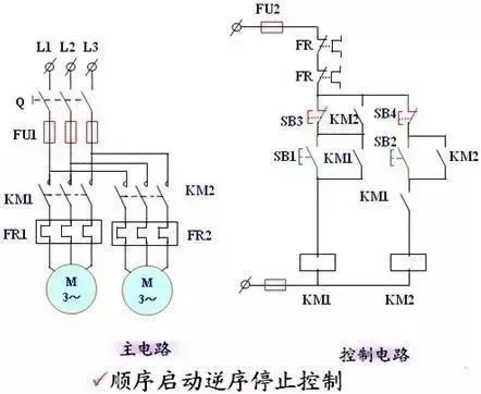
(2) Use the reverse reading and tracing method to decompose multiple loads (such as multi-motor circuits) into single load (such as single motor) circuits
According to the main contact symbol of the control appliance that controls the load in the main circuit, find the output relay of the contactor coil that controls the load in the PLC I/O wiring diagram, and then find the coil that controls the output relay and its related circuits in the ladder diagram and instruction statement table. This is the local circuit that controls the load.
In the ladder diagram and instruction statement table, it is easy to find the coil circuit of the output relay and its energizing and de-energizing conditions, but it is not easy to find the energizing and de-energizing of the coil and its related circuits. You can use the reverse reading and tracing method to find them:
The closing and opening of the contacts of other programming elements connected in series and parallel in the output relay coil circuit are the conditions for the output relay to be energized or de-energized.
From these contacts, we can find out their coil circuits and related circuits. In these coil circuits, there will be contacts of other contactors and relays...
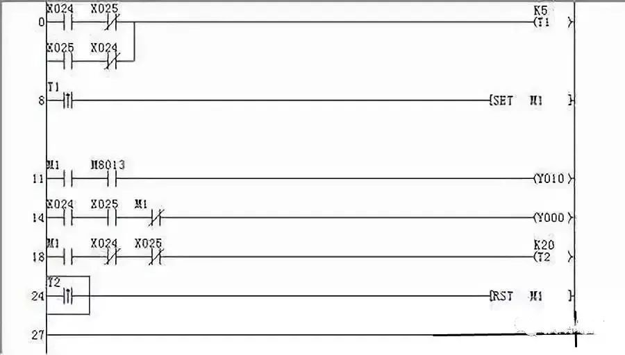
Continue searching in this way until you find the input relay (master control device). It is worth noting that when a programming element is energized or released, the action states of the previous and subsequent programming elements driven by all the contacts of the programming element should be found out without omission.
Find out the normally made contacts and normally broken contacts of a programming element in other circuits. These contacts provide conditions for the power on and off of other programming elements or for interlocking and interlocking, causing other electrical elements to operate and drive the executing electrical appliances.
(3) Further decomposition of the single load circuit
The local circuit for controlling a single load may still be complex and needs to be further decomposed into basic unit circuits.
(4) Notes on circuit decomposition
If the motor shaft is connected to a speed relay, the motor will form a parking brake circuit according to the speed control principle.
If a rectifier is connected to the main circuit of the motor, it indicates that the motor uses an energy-consuming braking parking circuit.
(5) Comprehensive analysis
Connect the basic unit circuits in series and use the forward tracking method to analyze the entire circuit.
Previous article:DC motor control principle and drive circuit often used in ROS learning platform
Next article:How to ground PLC? The purpose of PLC grounding
Recommended ReadingLatest update time:2024-11-16 10:35


- Popular Resources
- Popular amplifiers
- Huawei's Strategic Department Director Gai Gang: The cumulative installed base of open source Euler operating system exceeds 10 million sets
- Analysis of the application of several common contact parts in high-voltage connectors of new energy vehicles
- Wiring harness durability test and contact voltage drop test method
- Sn-doped CuO nanostructure-based ethanol gas sensor for real-time drunk driving detection in vehicles
- Design considerations for automotive battery wiring harness
- Do you know all the various motors commonly used in automotive electronics?
- What are the functions of the Internet of Vehicles? What are the uses and benefits of the Internet of Vehicles?
- Power Inverter - A critical safety system for electric vehicles
- Analysis of the information security mechanism of AUTOSAR, the automotive embedded software framework
 Professor at Beihang University, dedicated to promoting microcontrollers and embedded systems for over 20 years.
- Innolux's intelligent steer-by-wire solution makes cars smarter and safer
- 8051 MCU - Parity Check
- How to efficiently balance the sensitivity of tactile sensing interfaces
- What should I do if the servo motor shakes? What causes the servo motor to shake quickly?
- 【Brushless Motor】Analysis of three-phase BLDC motor and sharing of two popular development boards
- Midea Industrial Technology's subsidiaries Clou Electronics and Hekang New Energy jointly appeared at the Munich Battery Energy Storage Exhibition and Solar Energy Exhibition
- Guoxin Sichen | Application of ferroelectric memory PB85RS2MC in power battery management, with a capacity of 2M
- Analysis of common faults of frequency converter
- In a head-on competition with Qualcomm, what kind of cockpit products has Intel come up with?
- Dalian Rongke's all-vanadium liquid flow battery energy storage equipment industrialization project has entered the sprint stage before production
- Allegro MicroSystems Introduces Advanced Magnetic and Inductive Position Sensing Solutions at Electronica 2024
- Car key in the left hand, liveness detection radar in the right hand, UWB is imperative for cars!
- After a decade of rapid development, domestic CIS has entered the market
- Aegis Dagger Battery + Thor EM-i Super Hybrid, Geely New Energy has thrown out two "king bombs"
- A brief discussion on functional safety - fault, error, and failure
- In the smart car 2.0 cycle, these core industry chains are facing major opportunities!
- The United States and Japan are developing new batteries. CATL faces challenges? How should China's new energy battery industry respond?
- Murata launches high-precision 6-axis inertial sensor for automobiles
- Ford patents pre-charge alarm to help save costs and respond to emergencies
- New real-time microcontroller system from Texas Instruments enables smarter processing in automotive and industrial applications
- ZigBee acquisition system code is needed
- How to change incremental encoder into absolute encoder
- 【AT-START-F403A Review】+ Comparison between AT32F403A and GD32450I
- Share the experience of using GD32F10x and solve the problem
- Different routing layers, same STUB
- Are ADC accuracy and resolution the same thing?
- Won't boot!!! How wrong is this schematic?
- EEWORLD University ---- RISC-V Processor Design Series
- [NUCLEO-L552ZE Review] +RT-Thread Porting
- Single source shortest path - Dijkstara algorithm

 Siemens PLC Programming Technology and Application Cases (Edited by Liu Zhenquan, Wang Hanzhi, Yang Kun, etc.)


 京公网安备 11010802033920号