1. The execution process of Mitsubishi PLC return to origin program: Pulse output returns to the origin at high speed. When the origin switch is detected, it decelerates and runs. When the speed reaches the crawling speed, it reverses and returns at the crawling speed.

2. How to distinguish between air switch and isolating switch Air switch QF Isolating switch QS

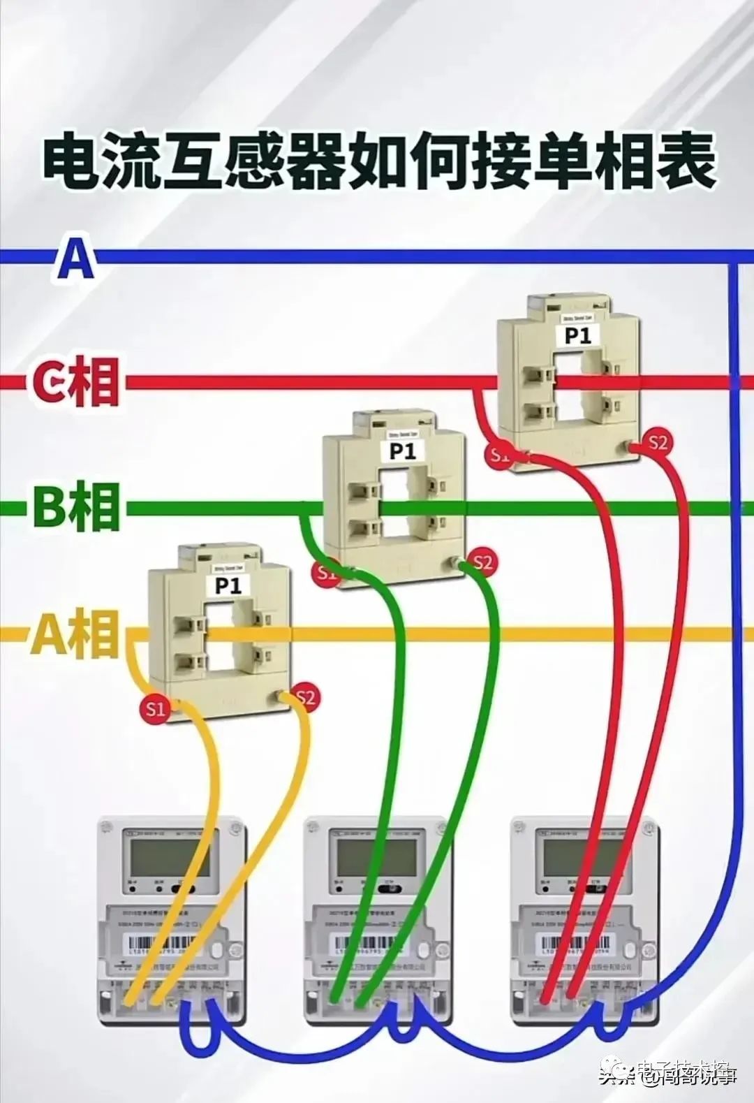
3. How to connect the current transformer to the single-phase meter

4. Three basic quantities you need to know when learning PLC Digital quantity: 0 and 1 ON OFF Analog quantity: voltage, current, pressure, speed, etc. Pulse quantity: rising edge and falling edge

5. Judging the resistance value from the color: Brown is one, red is two, orange is three, four, yellow is five, green is six, blue is seven, purple is eight, gray is nine, white is tight, five, silver is ten, table error


6. The data types that must be learned in PLC: bit, byte, word, double word, integer, double integer, real number, etc.

7. Selection of motor power and current wires

8. Forward and reverse control relay circuit

9.PLC controls forward and reverse rotation

10. Comparison between circuit diagram and PLC program diagram

11. Common alphabetic symbols for electricians

12. The difference between electrical diagram and PLC ladder diagram

13. Conversion and relationship between analog and digital quantities

14.Electrical control and PLC program

15. Two working modes after PLC is powered on: running mode and stop mode

16. How to identify the contactor coil

17. Choose the appropriate accessories according to the motor power

18. Introduction to common electrical instruments

19.Electrical forward and reverse control circuit

20. Electrician's Troubleshooting Tips

21. Nameplate parameters of three-phase asynchronous motor

Previous article:Simplify your motor control design with our digital signal controllers
Next article:PLC controls the speed and angle of the stepper motor. What components does the PLC control cabinet consist of?
Recommended ReadingLatest update time:2024-11-16 09:40


- Popular Resources
- Popular amplifiers
- Huawei's Strategic Department Director Gai Gang: The cumulative installed base of open source Euler operating system exceeds 10 million sets
- Analysis of the application of several common contact parts in high-voltage connectors of new energy vehicles
- Wiring harness durability test and contact voltage drop test method
- Sn-doped CuO nanostructure-based ethanol gas sensor for real-time drunk driving detection in vehicles
- Design considerations for automotive battery wiring harness
- Do you know all the various motors commonly used in automotive electronics?
- What are the functions of the Internet of Vehicles? What are the uses and benefits of the Internet of Vehicles?
- Power Inverter - A critical safety system for electric vehicles
- Analysis of the information security mechanism of AUTOSAR, the automotive embedded software framework
 Professor at Beihang University, dedicated to promoting microcontrollers and embedded systems for over 20 years.
- Innolux's intelligent steer-by-wire solution makes cars smarter and safer
- 8051 MCU - Parity Check
- How to efficiently balance the sensitivity of tactile sensing interfaces
- What should I do if the servo motor shakes? What causes the servo motor to shake quickly?
- 【Brushless Motor】Analysis of three-phase BLDC motor and sharing of two popular development boards
- Midea Industrial Technology's subsidiaries Clou Electronics and Hekang New Energy jointly appeared at the Munich Battery Energy Storage Exhibition and Solar Energy Exhibition
- Guoxin Sichen | Application of ferroelectric memory PB85RS2MC in power battery management, with a capacity of 2M
- Analysis of common faults of frequency converter
- In a head-on competition with Qualcomm, what kind of cockpit products has Intel come up with?
- Dalian Rongke's all-vanadium liquid flow battery energy storage equipment industrialization project has entered the sprint stage before production
- Allegro MicroSystems Introduces Advanced Magnetic and Inductive Position Sensing Solutions at Electronica 2024
- Car key in the left hand, liveness detection radar in the right hand, UWB is imperative for cars!
- After a decade of rapid development, domestic CIS has entered the market
- Aegis Dagger Battery + Thor EM-i Super Hybrid, Geely New Energy has thrown out two "king bombs"
- A brief discussion on functional safety - fault, error, and failure
- In the smart car 2.0 cycle, these core industry chains are facing major opportunities!
- The United States and Japan are developing new batteries. CATL faces challenges? How should China's new energy battery industry respond?
- Murata launches high-precision 6-axis inertial sensor for automobiles
- Ford patents pre-charge alarm to help save costs and respond to emergencies
- New real-time microcontroller system from Texas Instruments enables smarter processing in automotive and industrial applications
- Online Circuit Simulator
- Badge for the 2020 Open Hardware Summit
- Automatically exit at irregular intervals during while
- Intel Agilex M Series released! FPGA has better transmission layer efficiency and higher resource utilization
- ETU Configuration for CPU Card Programming
- MSP430 MCU printf function transplantation
- Disassembling Panasonic's antique tape recorder and analyzing its circuit design 50 years ago
- [Senior Science] What is an RF power amplifier? What are its applications?
- Release several sets of millimeter wave radar modules
- DSP clock and timer general timer

 Siemens PLC Programming Technology and Application Cases (Edited by Liu Zhenquan, Wang Hanzhi, Yang Kun, etc.)


 京公网安备 11010802033920号