The input circuits of various PLCs are roughly the same, and there are usually three types. One is DC 12~24V input, another is AC 100~120V, 200~240V input, and the third is AC/DC input. External input devices can be passive contacts or active sensor inputs. These external devices must be connected to the PLC through the PLC terminals and form a closed active loop, so power must be provided.
1. Wiring of passive switch
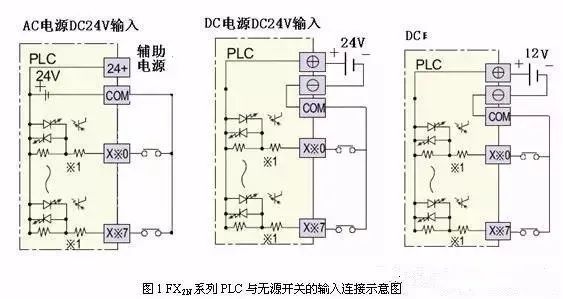
FX2N series PLC only has DC input, and inside the PLC, the input terminal is connected to the positive pole of the internal 24V power supply, and the COM terminal is connected to the negative pole, as shown in Figure 1. In this way, its passive switch input does not need to provide a separate power supply. This is very different from other types of PLCs. When using other PLCs in the future, you must pay attention to reading their instructions carefully.

2. Wiring of proximity switch
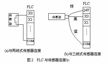
A proximity switch refers to a switch sensor that needs a power source to drive itself and outputs a certain voltage or current. There are many types of switch sensors based on their principles, which can be used for detection in different occasions, but they can be divided into three categories based on their signal lines: two-wire, three-wire, and four-wire. Among them, the four-wire type may provide a make contact and a break contact at the same time, but only one of them is used in practice; or the fourth line is the sensor verification line, which will not be connected to the PLC input terminal. Therefore, no matter which situation, the three-wire wiring can be referred to. Figure 2 is a schematic diagram of the connection between PLC and sensor.
The two-wire type has a signal line and a power line. The three-wire type has the positive and negative poles of the power supply and the signal line. Wires with different functions are represented by different colors. There are different ways to define this color. Please refer to the relevant instructions when using it. Figure 2(b) shows a common color definition. When the signal line is black, it is a make type; when the break type uses a white wire.

The sensor shown in the figure is NPN type, which is a common form. For the connection of PNP type sensor and PLC, you cannot copy this connection and refer to the corresponding information.
3. Wiring of rotary encoder
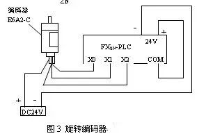
Rotary encoders can provide high-speed pulse signals and are often used in CNC machine tools and industrial control. Different types of encoders have different output frequencies and phases. Some encoders output three-phase pulses A, B, and C, some only have two-phase pulses, and some only have one-phase pulses (such as phase A). The frequencies are 100 Hz, 200 Hz, 1k Hz, 2k Hz, etc. When the frequency is relatively low, the PLC can respond; when the frequency is high, the PLC cannot respond. At this time, the output signal of the encoder must be connected to a special function module, such as the FX2N-11C using the FX2N-11HC high-speed counting module.

4. Mitsubishi PLC terminal wiring diagram
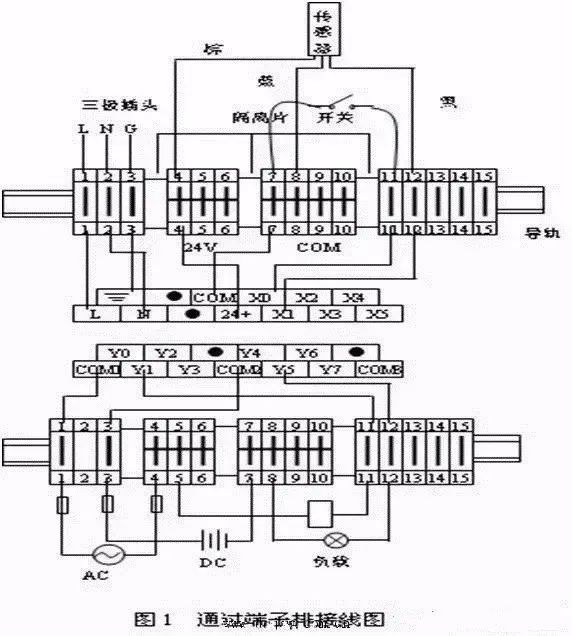
In engineering practice, it is impossible for all input and output devices to be directly connected to the PLC. Moreover, multiple output terminals of the PLC share a common COM terminal, and it is impossible to connect several or even dozens of wires to one terminal, so they must be connected through terminal blocks.
The terminal block is usually composed of multiple terminals installed side by side on the guide rail. The two ports of each terminal are short-circuited, and the terminals can be short-circuited together as needed.

Previous article:Servo motor definition Servo type selection
Next article:Servo motors and stepper motors FAQ
Recommended ReadingLatest update time:2024-11-16 09:46


- Popular Resources
- Popular amplifiers
- Huawei's Strategic Department Director Gai Gang: The cumulative installed base of open source Euler operating system exceeds 10 million sets
- Analysis of the application of several common contact parts in high-voltage connectors of new energy vehicles
- Wiring harness durability test and contact voltage drop test method
- Sn-doped CuO nanostructure-based ethanol gas sensor for real-time drunk driving detection in vehicles
- Design considerations for automotive battery wiring harness
- Do you know all the various motors commonly used in automotive electronics?
- What are the functions of the Internet of Vehicles? What are the uses and benefits of the Internet of Vehicles?
- Power Inverter - A critical safety system for electric vehicles
- Analysis of the information security mechanism of AUTOSAR, the automotive embedded software framework
 Professor at Beihang University, dedicated to promoting microcontrollers and embedded systems for over 20 years.
- Innolux's intelligent steer-by-wire solution makes cars smarter and safer
- 8051 MCU - Parity Check
- How to efficiently balance the sensitivity of tactile sensing interfaces
- What should I do if the servo motor shakes? What causes the servo motor to shake quickly?
- 【Brushless Motor】Analysis of three-phase BLDC motor and sharing of two popular development boards
- Midea Industrial Technology's subsidiaries Clou Electronics and Hekang New Energy jointly appeared at the Munich Battery Energy Storage Exhibition and Solar Energy Exhibition
- Guoxin Sichen | Application of ferroelectric memory PB85RS2MC in power battery management, with a capacity of 2M
- Analysis of common faults of frequency converter
- In a head-on competition with Qualcomm, what kind of cockpit products has Intel come up with?
- Dalian Rongke's all-vanadium liquid flow battery energy storage equipment industrialization project has entered the sprint stage before production
- Allegro MicroSystems Introduces Advanced Magnetic and Inductive Position Sensing Solutions at Electronica 2024
- Car key in the left hand, liveness detection radar in the right hand, UWB is imperative for cars!
- After a decade of rapid development, domestic CIS has entered the market
- Aegis Dagger Battery + Thor EM-i Super Hybrid, Geely New Energy has thrown out two "king bombs"
- A brief discussion on functional safety - fault, error, and failure
- In the smart car 2.0 cycle, these core industry chains are facing major opportunities!
- The United States and Japan are developing new batteries. CATL faces challenges? How should China's new energy battery industry respond?
- Murata launches high-precision 6-axis inertial sensor for automobiles
- Ford patents pre-charge alarm to help save costs and respond to emergencies
- New real-time microcontroller system from Texas Instruments enables smarter processing in automotive and industrial applications
- IoT development kits simplify application design
- Hands-on experience with Erha's image recognition artificial intelligence vision sensor.
- [Project source code] Set a password for the root of the Ubuntu system
- Pingtouge RVB2601 board-GUI and operating system tasks
- MSP430G2553ADC conversion program
- How to choose the right fuse for your design
- Build an IP surveillance camera system using low-cost FPGA
- Microwave Heating Principle
- 【Development Kit for nRF52840】+ Hardware Review
- [Repost] Comparison between aluminum electrolytic capacitors and tantalum capacitors

 Siemens PLC Programming Technology and Application Cases (Edited by Liu Zhenquan, Wang Hanzhi, Yang Kun, etc.)


 京公网安备 11010802033920号