"Good morning. It's 7am and the weather in Malibu is 72 degrees..." These are the first words JARVIS says when he is introduced in the Marvel Cinematic Universe. Most Iron Man fans should be able to recall this scene and remember that JARVIS is able to open a window in the morning (sort of) and provide an update on the time and weather. In the movie, the window glasses are actually made of a transparent touch display, so JARVIS is able to make it change from black to transparent and display weather statistics on it. However, in reality, we are still far away from see-through touch screens, and the closer we are to automatic control of blinds or restraints.
So in this project we are going to build exactly that, we are going to build an automatic electric blinds which will automatically open and close at predefined times.
Components Needed to Build an Arduino Automatic Blinds
This project is relatively simple and requires very few components. Simply gather the items listed below.
Node MCU
Stepper Motor – 28BYJ-48
Stepper motor driver module
LM117-3.3V
Capacitor (10uf, 1uf)
12V DC adapter
Performance Board
Welding Kit
3D Printer
Controlling roller shutters with Arduino
There are many different types of blinds on the market today, but the most commonly used ones are a string with beads on it (pictured below) that can be pulled to open or close the blind.
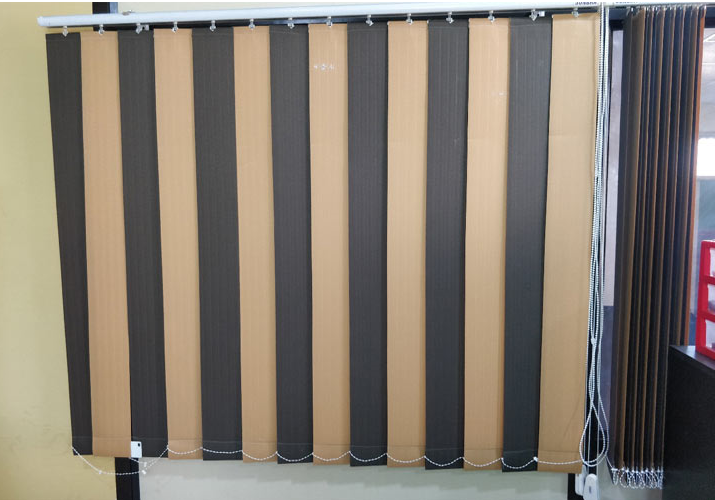
When we pull this circular rope in a clockwise direction, the blinds will open, and when we pull this rope in a counterclockwise direction, the blinds will close. So if we want to automate this process, all we have to do is use a motor to pull this rope in a clockwise or counterclockwise direction, and we will be done with it. In fact, that is what we will do in this project; we will use a 28BYJ-48 stepper motor and a NodeMCU to pull the bead rope.
Design and manufacture of window shutter gear
The electronics part of this project is fairly simple and straight forward, the challenging part is building the blind gear that can pull the beaded string. So let's start this post with the blind gear design, I'm not going to go into detail on how to design the gear but this basic concept should help you. An image of the string with the beads is shown below.

Again, there are many types of rope, but the most commonly used rope is one with a 6mm center to center distance between each bead and a 4mm diameter per bead. Using this information, we can start designing our gear. If the rope on your blind is the same dimensions as discussed, you can skip this step and download the STL file provided with this article and print the gear. If your rope has a different bead arrangement, then this is how you should redesign the blind gear.
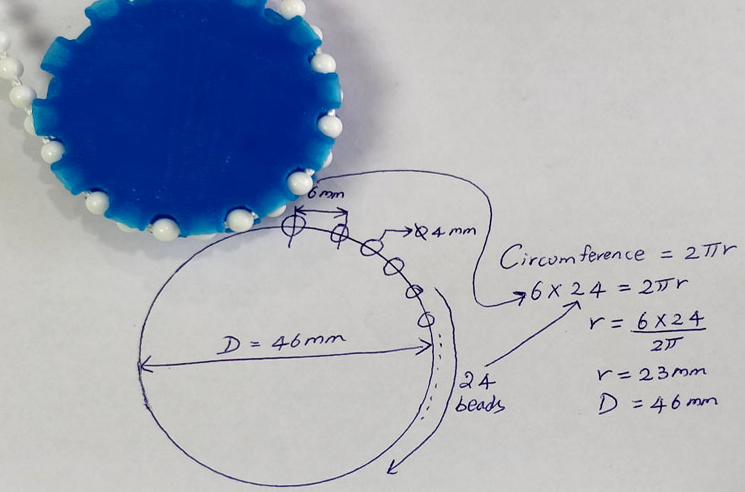
I decided to go with 24 beads on my gear to get the best gear size, you can choose any number close to this to make your gear bigger or smaller. So now, we know that the distance between each bead is 6mm, and we need 24 beads on our gear. Multiplying the two together will give you the circumference of the gear. With this data, you can calculate the radius of the gear. As you can see in the image above, the diameter of my gear is calculated to be about 46mm. But remember, this is not the actual diameter of the gear because we didn't take into account the 4mm bead diameter. Therefore, the actual diameter of the gear is 42mm, I printed and tested many gears before finding the one that worked best.
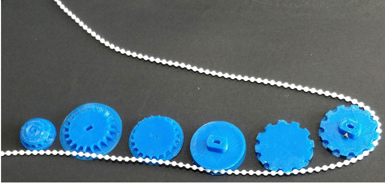
3D printed motor bracket and blind gear
In addition to the gears we will also need a small enclosure that can be drilled into the wall and hold the stepper motor in place, the enclosure and gears used in this project are shown below.
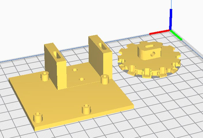
You can find the complete design files and STL files on the Arduino Blind Control Thingiverse page given below. You can download and print your blind gear and motor box.
Arduino blinds control circuit diagram
Once you have the gears and components ready, it is easy to proceed with the electronics and software part. The complete circuit diagram of the IoT Blind Control project is shown below.
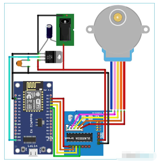
We use a 12V adapter to power the entire setup; the LM1117-3.3V regulator converts the 12V to 3.3V which can be used to power the NodeMCU board. The stepper motor driver module is powered directly from the 12V adapter. I did try running the stepper motors on 5V but it did not provide enough torque to pull the blinds, so make sure you use 12V as well.
Other than that the circuit is pretty straightforward, if you are not familiar with stepper motors check out the basics of stepper motors article to learn how it works and how to use it with a microcontroller.
Blynk app for Arduino blind control
Before we jump into the Arduino program for controlling the blinds, let's open the blynk app and create some buttons with which we can open or close the blinds. We will also need it later to control it from Google Home.
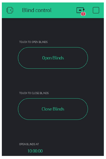
I have just added two buttons to open and close the blinds and a one timer to open the blinds at 10:00 AM every day. You can add multiple timers to open or close the blinds at different intervals throughout the day. Basically, when we have to close the blinds, we have to trigger the virtual pin V1 and when we have to open the blinds, we have to trigger the virtual pin V2. The program to control the stepper motor based on the buttons pressed here will be written on the Arduino IDE and the same will be discussed below.
Programming NodeMCU to control blinds using Blynk
The complete ESP8266 code for this blind control project can be found at the bottom of this page. Our program has to wait for a command from the blynk app and based on that command we have to rotate the stepper motor in either clockwise or counterclockwise direction. The important parts of the code are discussed below.
According to our circuit diagram, we use digital pins 1, 2, 3, and 4 on the NodeMCU to control our stepper motor. Therefore, we must create an instance called stepper using these pins as shown below. Note that we defined the pins in the order 1, 3, 2, and 4. This is intentional and not a mistake; we must swap pins 2 and 3 for the motor to work properly.
// Create an instance of the Stepper class with the steps and pins
Stepping advancers (STEPS, D1, D3, D2, D4);
In the next step, we have to share our blynk app authentication token and the Wi-Fi credentials that our IoT Blind controller has to connect to. If you are not sure how to get this Blynk authentication token, refer to the Blynk LED Control project to learn the basics of the blynk app and how to use it.
// You should get the Auth Token in Blynk App.
// Go to project settings (nut icon).
char auth[] = "l_b47mF1hioCc_7FzdKMJJeFnJjTxxxx";
// Your WiFi credentials.
// Set the password to "" for open networks.
char ssid[] = "Circuit Abstracts";
char pass[] = "dummy123";
Continuing with our code, after the setup function, we define two methods for Blynk. As mentioned earlier, we have to define what the virtual pins V1 and V2 should do. The code for the same is given below.
BLYNK_WRITE (V1) //Close the blinds
{
Serial.println("Close the blinds");
if (open == true)
{
for (int c_val = 0; c_val <= 130; c_val++) //Counterclockwise rotation to close
{
stepper.step(c_val);
yield();
}
closed = true;
open = false;
disableMotors(); //Always disable stepper motors after use to reduce power consumption and heating
}
}
BLYNK_WRITE(V2) // Open the blinds
{
Serial.println("Open the blinds");
if (close == true)
{
for (int cc_val = 0; cc_val >= -130; cc_val--) // Open by rotating clockwise
{
stepper.step(cc_val);
yield();
}
open = true;
closed = false;
}
disableMotors(); //Always disable stepper motors after use to reduce power consumption and heating
}
As you can see, V1 is used to close the blinds and V2 is used to open the blinds. The for loop is used to rotate the motor 130 steps in either a clockwise or counterclockwise direction. I experimented with my blinds and found that with 130 steps, I was able to fully open and close my blinds. Your numbers may vary. The for loop used to rotate the stepper motor in both clockwise and counterclockwise directions is shown below.
for (int c_val = 0; c_val <= 130; c_val++) //Counterclockwise rotation to close
{
stepper.step(c_val);
yield();
}
for (int cc_val = 0; cc_val >= -130; cc_val--) // Open by rotating clockwise
{
stepper.step(cc_val);
yield();
}
You may also notice two Boolean variables "open" and "closed" in our program. These two variables are used to prevent the motor from opening or closing the blinds twice. Meaning, the blinds will only open if they were previously closed, and will only close if they were previously opened.
How to increase the speed of 28BJY-48 stepper motor?
One disadvantage of using 28BJY-48 stepper motors is that they are slow. These motors were originally made for high precision low speed applications, so don't expect these motors to spin at high speeds. If you want to increase the speed of a stepper motor using an Arduino, there are two parameters you can change. One is #define STEPS 64, I have found that when steps is defined as 64, the motor is relatively faster. The other parameter is stepper.setSpeed(500); again I have found 500 to be an optimal value, anything above this actually makes the stepper motor slower.
Do you know of other ways to increase the speed of these motors? If so, please leave them in the comments section below.
How to prevent stepper motors from overheating?
Stepper motors should always be disabled when not in use to prevent overheating. Disabling a stepper motor is very simple; just change the pin state of all four GPIO pins that control the stepper motor to low. This is very important, otherwise your motor may get very hot at +12V and permanently damage itself. Given below is the procedure to disable a stepper motor.
Previous article:Build a simple home automation system based on Arduino
Next article:How to use KY-037 Sound Detection Sensor with Arduino
Recommended ReadingLatest update time:2024-11-16 10:30

- Huawei's Strategic Department Director Gai Gang: The cumulative installed base of open source Euler operating system exceeds 10 million sets
- Analysis of the application of several common contact parts in high-voltage connectors of new energy vehicles
- Wiring harness durability test and contact voltage drop test method
- Sn-doped CuO nanostructure-based ethanol gas sensor for real-time drunk driving detection in vehicles
- Design considerations for automotive battery wiring harness
- Do you know all the various motors commonly used in automotive electronics?
- What are the functions of the Internet of Vehicles? What are the uses and benefits of the Internet of Vehicles?
- Power Inverter - A critical safety system for electric vehicles
- Analysis of the information security mechanism of AUTOSAR, the automotive embedded software framework
 Professor at Beihang University, dedicated to promoting microcontrollers and embedded systems for over 20 years.
- Innolux's intelligent steer-by-wire solution makes cars smarter and safer
- 8051 MCU - Parity Check
- How to efficiently balance the sensitivity of tactile sensing interfaces
- What should I do if the servo motor shakes? What causes the servo motor to shake quickly?
- 【Brushless Motor】Analysis of three-phase BLDC motor and sharing of two popular development boards
- Midea Industrial Technology's subsidiaries Clou Electronics and Hekang New Energy jointly appeared at the Munich Battery Energy Storage Exhibition and Solar Energy Exhibition
- Guoxin Sichen | Application of ferroelectric memory PB85RS2MC in power battery management, with a capacity of 2M
- Analysis of common faults of frequency converter
- In a head-on competition with Qualcomm, what kind of cockpit products has Intel come up with?
- Dalian Rongke's all-vanadium liquid flow battery energy storage equipment industrialization project has entered the sprint stage before production
- Allegro MicroSystems Introduces Advanced Magnetic and Inductive Position Sensing Solutions at Electronica 2024
- Car key in the left hand, liveness detection radar in the right hand, UWB is imperative for cars!
- After a decade of rapid development, domestic CIS has entered the market
- Aegis Dagger Battery + Thor EM-i Super Hybrid, Geely New Energy has thrown out two "king bombs"
- A brief discussion on functional safety - fault, error, and failure
- In the smart car 2.0 cycle, these core industry chains are facing major opportunities!
- The United States and Japan are developing new batteries. CATL faces challenges? How should China's new energy battery industry respond?
- Murata launches high-precision 6-axis inertial sensor for automobiles
- Ford patents pre-charge alarm to help save costs and respond to emergencies
- New real-time microcontroller system from Texas Instruments enables smarter processing in automotive and industrial applications
- I have a question, STM32 drives a three-phase DC brushless controller to drive a DC brushless motor with Hall
- An employee was dissatisfied with being fired and used a "crawler" to delete company data
- Welcome to the 5G era: There are countermeasures for mobile phone antenna design
- Allegro board layer color configuration
- Detailed explanation of series/parallel resonant circuit
- EEWORLD University ---- Medical monitoring and wearable devices
- Photodetector Array Signal Processing
- Can cam350 export individual component packages based on gerber files?
- Application of wireless power transmission technology in underwater transmission
- Can the differential pairs be wound with equal lengths like this?


 Arduino UNO R4 WiFi Engineering Code
 Workplace Refresher Project Code
 TLE2061CPSR


 京公网安备 11010802033920号