Candles have been very useful since ancient times, guiding mankind at night even before Edison came up with the idea of the light bulb. Today, from churches to kitchens, candles not only provide lighting when needed, but also add beauty and provide a sense of warmth. While regular candles work fine, they quickly melt, making the place dirty and sometimes also a fire hazard if left unattended. So, in this tutorial, we will use some simple electronics and LEDs to make a flameless electronic candle. Moreover, this smart candle will automatically turn on at night or in the dark and turn off during the day.
Required Materials
LM358 Integrated Circuit
LDR (Light Dependent Resistor)
1M and 1K resistors
Light Emitting Diode
10K Pot
12V female DC power jack and 12V adapter
Cardstock and perforated board
LM358 – Operational Amplifier Comparator
The brains behind this circuit is the LM358 IC, which acts as a comparator in this particular design. Before we dive in, let’s take a brief look at what it is. The LM358 is an Operational Amplifier (Op Amp) IC. This IC consists of two operational amplifiers that can handle voltages between 3.3V to 32V and has a very low supply current consumption of 500μA. The IC looks like this:
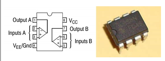
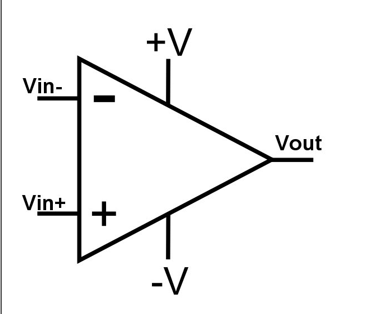
It is commonly used to build simple comparator and amplifier circuits and can also be found in active filter circuits, waveform shapers, etc. In this project, we will use LM358 as a voltage comparator. Voltage comparator is used to compare two voltages and find out which one is greater than the other and then turns the output high or low based on that voltage. So, if we apply voltage to the inverting and non-inverting inputs and if the voltage on the non-inverting input is greater than the voltage on the inverting input, then the output becomes high and vice versa, the output becomes low. This project works exactly on this principle. The voltage comparison formula is given below:
V OUT =AO (V in+ - V in- )
Where AO is the open loop gain of the operational amplifier. Vin+ is the input voltage at the non-inverting input and Vin- is the input voltage at the inverting input. Therefore, if Vin+ is greater than Vin- then the output will be high, otherwise it will be low.
LDR
If the op-amp is the brain of our circuit, then the LDR is the sensory organ. A light-dependent resistor (LDR) or photoresistor is a light-controlled resistor. Its resistance decreases as the light intensity increases and vice versa. In fact, when light is incident on the LDR, the semiconductor absorbs the photons of light, the bonding electrons jump to the conduction band, and the resistance decreases due to photoconductivity.

Circuit diagram and description
The circuit is not difficult. Given below is the complete circuit diagram of the electronic candle.
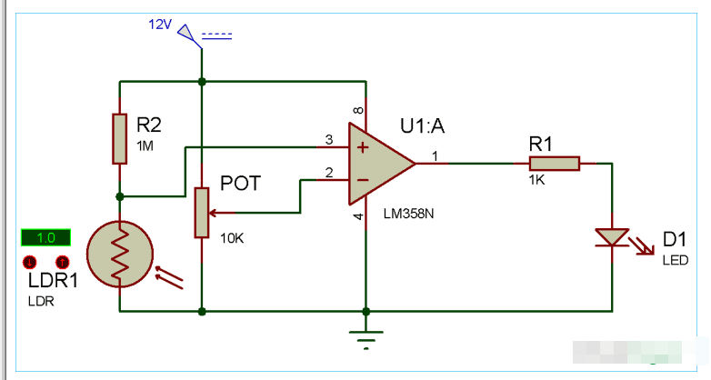
As shown in the circuit diagram, connect a 1K resistor to pin 1 of the IC and then connect the positive leg of the LED to this resistor and the negative leg to ground. Now connect the middle pin of the 10K potentiometer to pin 2 of the IC and connect ground and 12V to the remaining pins of the potentiometer. Connect a 1M resistor to 12V and connect the LDR in series with this resistor. Now, connect the other end of the LDR to the ground of the circuit. Connect the common point of the LDR and the 1M resistor to pin 3 of the IC. Connect 12V to pin 8 and ground to pin 4 of the IC and you are ready. You don't need to be very picky about the resistors, we have already connected them. But make sure the resistor connected to the LDR is megohms and the resistor with the LED is a few thousand.
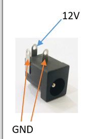
We built the complete circuit on a dummy board to make it compact and easy to use. It really is a simple circuit, you just need to sharpen your soldering skills and start designing it. First, mount the 12V female DC power jack on the perfboard. Keep the pin configuration of this jack in mind while designing the circuit. As shown in the image below:
As we have discussed above about the pinout of op-amp, resistors and LDR have no polarity. After the soldering work is completed, the board should look like the following image.

Smart Electric Candle - Working
After designing the circuit on the perfboard and soldering it, connect the 12V adapter to the female jack and your LED must glow. Now, to calibrate the comparator, adjust the 10K potentiometer to a level where the LED just turns off. Now cover the LDR with your hand and you will see the LED light up. You can adjust the sensitivity of the LDR by adjusting the potentiometer.
Now, let's understand how this candle works. As we already know, in darkness, the resistance of the LDR increases to megohms and decreases to a few hundred ohms as the light intensity increases. So since the resistance is very low, the voltage across the non-inverting signal is very low compared to the inverting end, because we have connected the 10K pot. So in this case, the output voltage is also low, so the LED does not turn on. But in darkness, the resistance increases to megohms, which is very high compared to the 10K pot, so the LED glows.
Adjusting the pot will manipulate the sensitivity. By sensitivity, I mean at what intensity of light your comparator turns on the LED. If you adjust the pot close to the LED, then it will detect tiny darkness as well. But if you adjust it far away before the LED lights up, then it will only detect high darkness. You can also test the sensitivity by placing your hand in front of the LDR. If it detects your hand far away, it is highly sensitive, if you need to cover it to light up the LED, it is not that sensitive.
If you want to use multiple LEDs then it's not a problem. Connect two or three LEDs in series and finally connect them to where we connected a single LED and its perfect. But make sure your comparator can provide enough current to power all the LEDs.
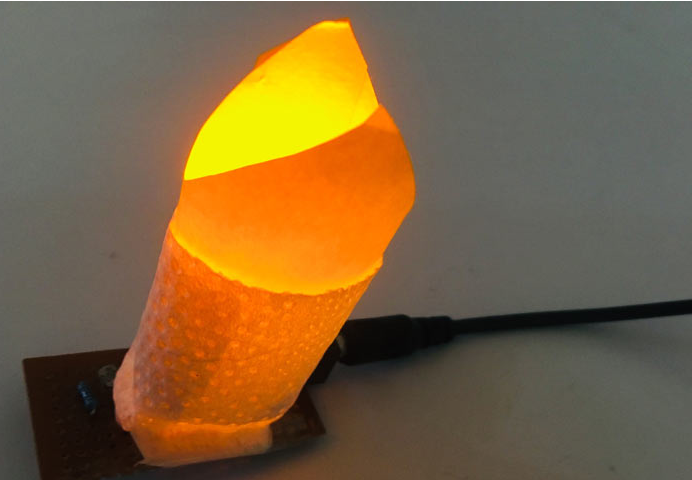
To make the candle, you can use anything to cover the LED. I used card stock and tissue paper. Roll up the card according to the size of the LED and cut a flame shape or any shape you want from it to make it look attractive. Cover the LED with this candle and you have made your own smart electronic candle.
Previous article:24V Handheld Vacuum Cleaner Solution Based on TMI82312
Next article:Modern digital approaches to microphone processing
Recommended ReadingLatest update time:2024-11-16 21:34

![[51 MCU Quick Start Guide] 2.4: 74HC595, LED dot matrix screen and its SPI control](https://6.eewimg.cn/news/statics/images/loading.gif)


- Popular Resources
- Popular amplifiers
- Huawei's Strategic Department Director Gai Gang: The cumulative installed base of open source Euler operating system exceeds 10 million sets
- Analysis of the application of several common contact parts in high-voltage connectors of new energy vehicles
- Wiring harness durability test and contact voltage drop test method
- Sn-doped CuO nanostructure-based ethanol gas sensor for real-time drunk driving detection in vehicles
- Design considerations for automotive battery wiring harness
- Do you know all the various motors commonly used in automotive electronics?
- What are the functions of the Internet of Vehicles? What are the uses and benefits of the Internet of Vehicles?
- Power Inverter - A critical safety system for electric vehicles
- Analysis of the information security mechanism of AUTOSAR, the automotive embedded software framework
 Professor at Beihang University, dedicated to promoting microcontrollers and embedded systems for over 20 years.
- Innolux's intelligent steer-by-wire solution makes cars smarter and safer
- 8051 MCU - Parity Check
- How to efficiently balance the sensitivity of tactile sensing interfaces
- What should I do if the servo motor shakes? What causes the servo motor to shake quickly?
- 【Brushless Motor】Analysis of three-phase BLDC motor and sharing of two popular development boards
- Midea Industrial Technology's subsidiaries Clou Electronics and Hekang New Energy jointly appeared at the Munich Battery Energy Storage Exhibition and Solar Energy Exhibition
- Guoxin Sichen | Application of ferroelectric memory PB85RS2MC in power battery management, with a capacity of 2M
- Analysis of common faults of frequency converter
- In a head-on competition with Qualcomm, what kind of cockpit products has Intel come up with?
- Dalian Rongke's all-vanadium liquid flow battery energy storage equipment industrialization project has entered the sprint stage before production
- Allegro MicroSystems Introduces Advanced Magnetic and Inductive Position Sensing Solutions at Electronica 2024
- Car key in the left hand, liveness detection radar in the right hand, UWB is imperative for cars!
- After a decade of rapid development, domestic CIS has entered the market
- Aegis Dagger Battery + Thor EM-i Super Hybrid, Geely New Energy has thrown out two "king bombs"
- A brief discussion on functional safety - fault, error, and failure
- In the smart car 2.0 cycle, these core industry chains are facing major opportunities!
- The United States and Japan are developing new batteries. CATL faces challenges? How should China's new energy battery industry respond?
- Murata launches high-precision 6-axis inertial sensor for automobiles
- Ford patents pre-charge alarm to help save costs and respond to emergencies
- New real-time microcontroller system from Texas Instruments enables smarter processing in automotive and industrial applications
- Arteli-AT32F4xx timer input capture mode
- How to capture the instantaneous waveform with an oscilloscope and automatically lock it?
- What is the difference between classic Bluetooth and Bluetooth Low Energy?
- Prize-giving activity - the embedded operating system I know
- MCU obtains the network camera video stream problem, please help! ! !
- msp430f5529 capture plus serial port source code
- Share: Regarding the 2021 eSports race, you must be familiar with these!
- Conversion from C to VHDL in SOC system.rar
- Learn knowledge and win gifts | Tektronix Semiconductor Materials and Device Test Technology Power Characteristics!
- EEWORLD University Hall----TI Robot System Learning Kit (TI-RSLK) Upgraded Version

 Siemens PLC Project Tutorial
 LED Cube Code
 ESP32-S3 source code


 京公网安备 11010802033920号