Siemens 200ppi to Ethernet to achieve Ethernet communication and ModbusTCP configuration method through CHNet-S7200PD
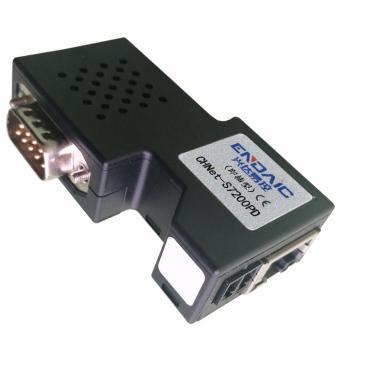
Product Introduction
CHNet-S7200 is used for Ethernet data acquisition of Siemens S7-200/SMART S7-200 PLC, which is very convenient for building production management system.
CHNet-S7200 does not occupy the PLC programming port, that is, while the programming software/host computer software monitors and collects PLC data through Ethernet, the touch screen can communicate with the PLC through the extended RS485 port.
CHNet-S7200 supports most SCADA software in the industrial control field, and supports Siemens S7TCP Ethernet protocol and ModbusTCP protocol.
CHNet-S7200PD straight-through type: CHNet's extended DSUB9-pin female port can connect to Siemens and Proface touch screens, multi-master cables, and communication boards;
CHNet-S7200PB bridge type: CHNet's extended DSUB 9-pin female port can be connected to non-Siemens touch screens, such as Kunlun Tongtai, Weilun, Delta, and Buke.
CHNet-S7200 Features:
1. Support multi-master station communication, the expansion port can be connected to the touch screen or other master stations.
2. Parameters of the device can be set and operation diagnosis can be performed through the WEB server or the configuration diagnostic tool NetDevice.
3. Baud rate 9.6Kbps~187.5Kbps adaptive.
4. Directly installed on the PPI communication port of PLC or the communication port of EM277, no external power supply is required.
5. Support Siemens S7 Ethernet communication driver, including MicroWIN, and support WinCC to connect directly to S7-200 via TCP/IP.
6. Users can use high-level programming languages (such as VB, VC, C#, etc.) according to the CHNetS7 protocol to achieve data communication with S7-200, which is convenient for developing production management systems.
7. Provide CHNetS7 OPC server free of charge, support OPC channel SCADA to communicate with PLC in OPC mode.
8. Integrated ModbusTCP server, Modbus data area can be automatically or edited and mapped to S7-200 registers.
9. It can realize S7TCP connection and ModbusTCP communication at the same time, and supports the connection of up to 32 host computers.
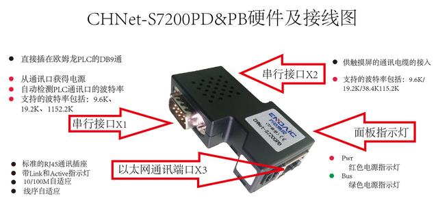
CHNet-200PD&PB hardware and wiring diagram:
Driver Installation
Before installing the programming driver, the computer must first have Siemens MicroWIN software, STEP7 software or TIA Portal software installed. There should be a "Set PG/PC Interface" icon in the control panel, as shown below:

If the computer's operating system is 32-bit, please install the 32-bit programming driver; if the computer's operating system is 64-bit, please install
64-bit programming driver. When installing, please right-click the driver and install it as [Run as Administrator]. After the installation is complete, please restart the computer.
【NetS7PD1801_setup_x86】 is a 32-bit programming driver;
【NetS7PD1802_setup_x64】 is a 64-bit programming driver.
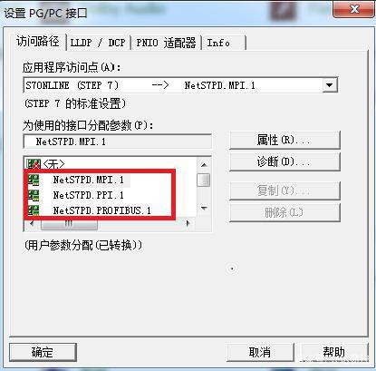
After restarting the computer, enter the control panel and open [Set PG/PC Interface], where you can see the newly added communication interface:
MicroWIN programming and debugging
There are two ways to program and debug the module with MicroWIN: through CHNet programming driver, or through Siemens Ethernet driver.
5.1.1 Driven by CHNet programming
1. Open MicroWIN software and click the [Set PG/PC Interface] icon in the left navigation bar;
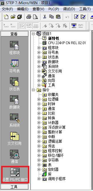
1. Select NetS7PD.PPI.1 in [Assign parameters to the interface used] and make sure [Application access point] is Micro/WIN
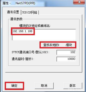
—>NetS7PD.PPI.1, click the [Properties] button;
2. If you know the IP address of the module, directly enter the IP address in [Module IP address or domain name] and click the [OK] button;
3. If you don't know the IP address of the module, you can click [Find local module], select the module to connect, and click the [Select device] button.
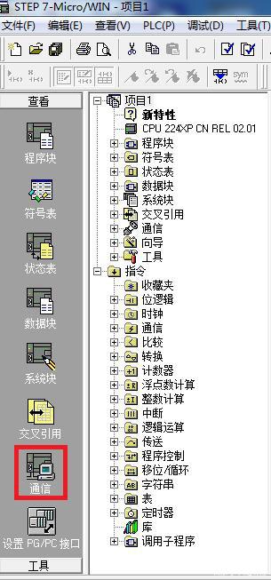
4. Click the [Communication] icon in the left navigation bar
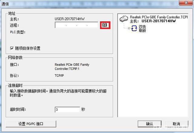
5. Double-click the [Double-click to refresh] icon, select the PLC to be refreshed, and click the [Confirm] button.

Via Siemens Ethernet driver
1. Open MicroWIN software and click the [Set PG/PC Interface] icon in the left navigation bar;

2. Select the computer's network card in [Assign parameters to the interface used] and make sure [Application access point] is Micro/WIN—>Computer
Network card, click the [OK] button;
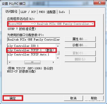
Note: Please select the computer network card with the suffix TCPIP
3. Click [Communication] in the left navigation bar;

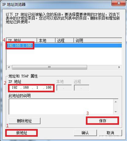
4. Click the icon below to open the IP address browser;
5. Click the [New Address] button, enter the module's IP address in [IP Address], click the [Save] button, and double-click the saved IP address;
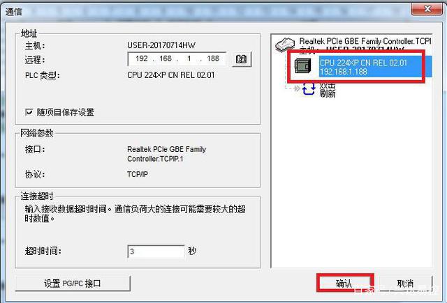
6. Double-click the [Double-click to refresh] icon, select the PLC to be refreshed, and click the [Confirm] button.
Previous article:How to implement Ethernet communication and ModbusTCP configuration through CHNet-S7300MD
Next article:Omron PLC to Ethernet via CHNet-CP and MatrikonOPC ModbusTCP communication configuration
- Popular Resources
- Popular amplifiers
-
 Automotive High Speed Communication Technologies: SerDes and Ethernet for Sensor and Display Applica
 -
 Pattern-Oriented Software Architecture Volume 4 A Pattern Language for Distributed Computing
 -
 National Industrial Robot Technology Application Skills Competition Preparation Guide
 -
 Embedded system development tips, a novice\'s growth log and a project manager\'s recipe
- Detailed explanation of intelligent car body perception system
- How to solve the problem that the servo drive is not enabled
- Why does the servo drive not power on?
- What point should I connect to when the servo is turned on?
- How to turn on the internal enable of Panasonic servo drive?
- What is the rigidity setting of Panasonic servo drive?
- How to change the inertia ratio of Panasonic servo drive
- What is the inertia ratio of the servo motor?
- Is it better for the motor to have a large or small moment of inertia?
 Professor at Beihang University, dedicated to promoting microcontrollers and embedded systems for over 20 years.
- LED chemical incompatibility test to see which chemicals LEDs can be used with
- Application of ARM9 hardware coprocessor on WinCE embedded motherboard
- What are the key points for selecting rotor flowmeter?
- LM317 high power charger circuit
- A brief analysis of Embest's application and development of embedded medical devices
- Single-phase RC protection circuit
- stm32 PVD programmable voltage monitor
- Introduction and measurement of edge trigger and level trigger of 51 single chip microcomputer
- Improved design of Linux system software shell protection technology
- What to do if the ABB robot protection device stops
- Detailed explanation of intelligent car body perception system
- How to solve the problem that the servo drive is not enabled
- Why does the servo drive not power on?
- What point should I connect to when the servo is turned on?
- How to turn on the internal enable of Panasonic servo drive?
- What is the rigidity setting of Panasonic servo drive?
- How to change the inertia ratio of Panasonic servo drive
- What is the inertia ratio of the servo motor?
- Is it better for the motor to have a large or small moment of inertia?
- What is the difference between low inertia and high inertia of servo motors?
- DE1-SOC development board usage learning
- The use of stack in DSP
- The display principle of the segment code screen, for example, to display the word high voltage, which two pins are driven, and high voltage is a character, isn't it...
- Embedded Computer System Development Process and Application Prospects
- Test Measurement Album!!
- [RVB2601 Creative Application Development] Chinese Display
- Challenge FreeRTOS learning + shell task implementation
- Global reset (GSR) in FPGA development
- [Gizwits Gokit3 Review] Device access-Step 3: Download the program firmware
- When a PCB designer encounters love, guess how much the impedance of his board changes

 Automotive High Speed Communication Technologies: SerDes and Ethernet for Sensor and Display Applica
 Embedded system development tips, a novice\'s growth log and a project manager\'s recipe


 京公网安备 11010802033920号