PLC is easy to use and has high reliability. The electrical control of many devices is mainly based on the I/O electrical interface of the switch quantity. The input end of the PLC is usually connected to the field instrument, various switches and other electrical components, and the output end of the PLC is usually connected to various types of actuators, such as electric and pneumatic actuators. There are also connections with relays, contactors, solenoid valves, etc.
For example, the connection of the switch input element is actually to connect or disconnect the input terminal of the PLC and its common terminal. Therefore, one end of the "switch" is connected to the PLC input terminal and the other end is connected to its common terminal.

How does PLC connect with common input and output electrical components?
The PLC looks like a black box, and the manufacturer usually only provides the input and output terminal wiring diagram. The essence of the circuit is to form a loop. Each input terminal corresponds to a loop, and each output terminal also corresponds to an output loop. As long as the loop is closed, current will be generated. When the input or output state changes, a connection will be established between the external circuit and the PLC.
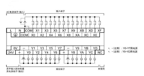
Common switch I/O connection method
In fact, PLC has many independent switch inputs and outputs, and there will be a common terminal COM (or S/S, etc.). Each switch input corresponds to a terminal such as X0 (or I0), and each switch output also corresponds to a terminal such as Y0 (or O0). For example, connect one end of the switch to be input to X0 and the other end to the common terminal COM. When the switch is activated, the state of the X0 signal will change.
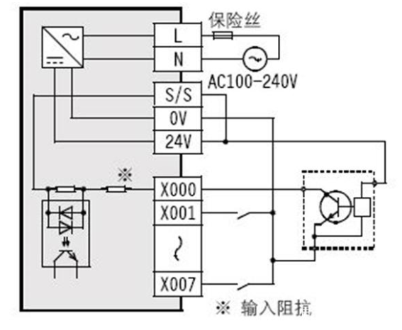
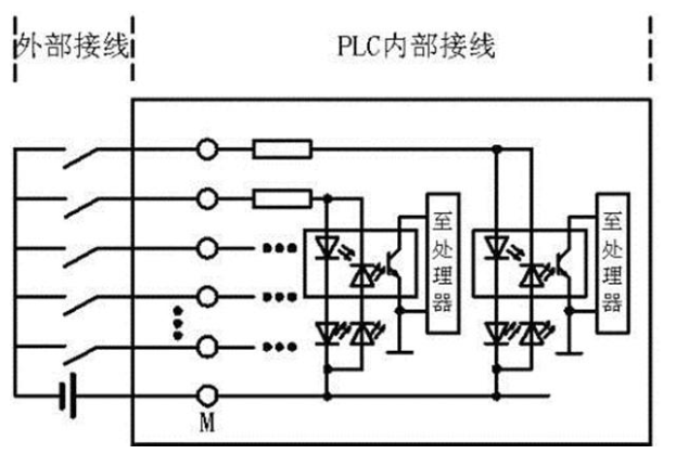
Basically, today's PLCs can accept input signals of either NPN or PNP type, because they use bidirectional optocouplers, which have light-emitting diodes in two directions, and current can flow in both directions, as long as you connect the wires correctly.
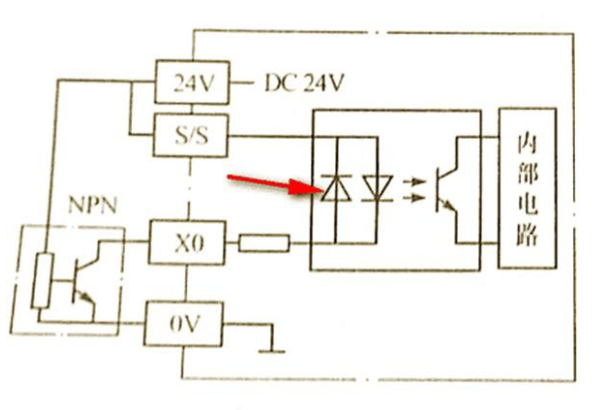
Some early Japanese PLCs can only accept NPN signals, that is, the input signal can only be a low level signal, so the current "leaks" out, so it is a so-called leakage input, and the common terminal COM (S/S) of the leakage input is grounded.
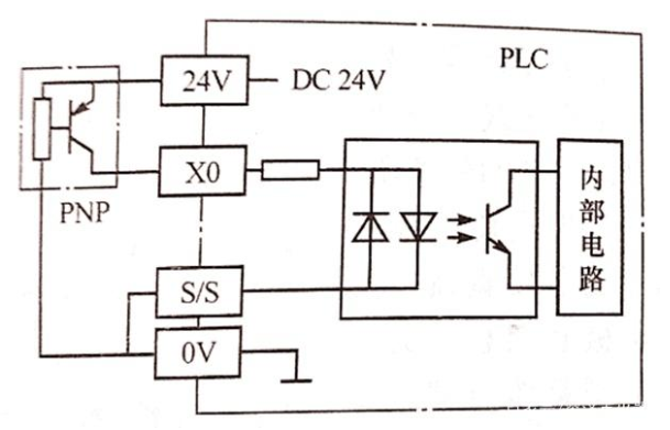
The other type can only accept PNP models, that is, the input signal can only be high level, so the current flows in through the external power supply, so it is called source input, and the source input common terminal COM (S/S) is connected to the positive pole.
By the same token, transistor outputs will also face this problem, because transistor outputs generally have NPN or PNP type transistors (or field effect transistors with similar structures) to provide peripheral circuits.
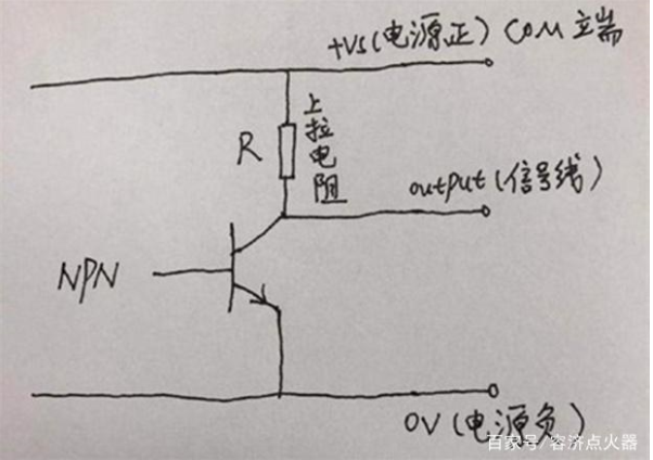
For example, the above picture is a schematic diagram of NPN type output. Generally, PLCs will have internal pull-up resistors (if not, they need to be added externally). The output signal line is on the PLC output terminal (such as Y0 or O0). When using it, you must pay attention to the maximum output current and calculate the impedance on the load side, otherwise it may burn out.

There will also be a PNP type output structure. The core inside is a PNP type transistor. There will be a pull-down resistor to the ground, and the output signal line also corresponds to the PLC output terminal (such as Y0 or O0).

As for the relay output, it is a passive contact, so there is no difference in direction. There is no need to consider common ground or common anode issues. There is no problem in connecting it in any way.
Other functional modules
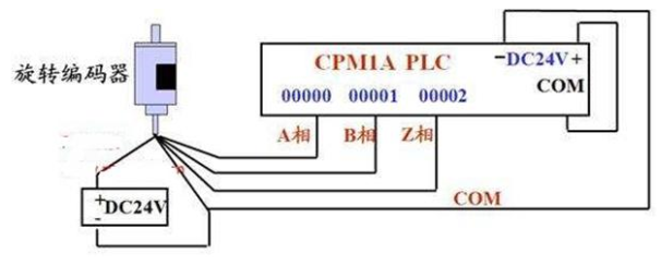
For example, high-speed counting ports, because high-speed optocouplers are more expensive than ordinary ones, and many microcontrollers only have certain ports that can respond at high speed.
The same is true for analog modules. Some I/Os will be specified with these functions, and you also need to read the manual to connect them. You also need to pay attention to the range of the input analog quantity and the nature of the signal, whether it is voltage or current type. Some require external resistors for conversion.
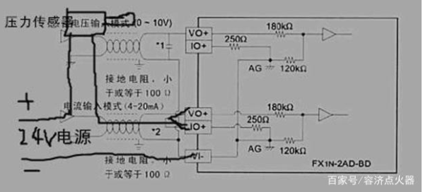
Regardless of the function, the wiring method is essentially the same as that of ordinary I/O, as long as a loop is formed. However, these special I/O or additional functional modules often require the use of frequency lines or twisted pair cables to avoid signal interference because of the large amount of data transmitted and the high frequency.
Previous article:Case Study on the Collection and Processing of Analog Quantity in PLC
Next article:Common wiring of PLC input and output terminals
Recommended ReadingLatest update time:2024-11-16 12:49


- Popular Resources
- Popular amplifiers
- Huawei's Strategic Department Director Gai Gang: The cumulative installed base of open source Euler operating system exceeds 10 million sets
- Analysis of the application of several common contact parts in high-voltage connectors of new energy vehicles
- Wiring harness durability test and contact voltage drop test method
- Sn-doped CuO nanostructure-based ethanol gas sensor for real-time drunk driving detection in vehicles
- Design considerations for automotive battery wiring harness
- Do you know all the various motors commonly used in automotive electronics?
- What are the functions of the Internet of Vehicles? What are the uses and benefits of the Internet of Vehicles?
- Power Inverter - A critical safety system for electric vehicles
- Analysis of the information security mechanism of AUTOSAR, the automotive embedded software framework
 Professor at Beihang University, dedicated to promoting microcontrollers and embedded systems for over 20 years.
- Innolux's intelligent steer-by-wire solution makes cars smarter and safer
- 8051 MCU - Parity Check
- How to efficiently balance the sensitivity of tactile sensing interfaces
- What should I do if the servo motor shakes? What causes the servo motor to shake quickly?
- 【Brushless Motor】Analysis of three-phase BLDC motor and sharing of two popular development boards
- Midea Industrial Technology's subsidiaries Clou Electronics and Hekang New Energy jointly appeared at the Munich Battery Energy Storage Exhibition and Solar Energy Exhibition
- Guoxin Sichen | Application of ferroelectric memory PB85RS2MC in power battery management, with a capacity of 2M
- Analysis of common faults of frequency converter
- In a head-on competition with Qualcomm, what kind of cockpit products has Intel come up with?
- Dalian Rongke's all-vanadium liquid flow battery energy storage equipment industrialization project has entered the sprint stage before production
- Allegro MicroSystems Introduces Advanced Magnetic and Inductive Position Sensing Solutions at Electronica 2024
- Car key in the left hand, liveness detection radar in the right hand, UWB is imperative for cars!
- After a decade of rapid development, domestic CIS has entered the market
- Aegis Dagger Battery + Thor EM-i Super Hybrid, Geely New Energy has thrown out two "king bombs"
- A brief discussion on functional safety - fault, error, and failure
- In the smart car 2.0 cycle, these core industry chains are facing major opportunities!
- The United States and Japan are developing new batteries. CATL faces challenges? How should China's new energy battery industry respond?
- Murata launches high-precision 6-axis inertial sensor for automobiles
- Ford patents pre-charge alarm to help save costs and respond to emergencies
- New real-time microcontroller system from Texas Instruments enables smarter processing in automotive and industrial applications
- [Last Week] Watch the Power Supply Seminar to Share a 3,000 RMB Red Packet - Learn How to Correctly Complete a Modular DC-DC System
- Solution to the failure of CCS8.0 and XDS100V3 emulators to connect to the target board
- [Nucleo G071 Review] Serial port 1 idle interrupt + DMA to achieve variable length reception
- SAMPCON for msp430
- 【DFRobot wireless communication module】SIM test
- How much do you know about flash memory technology?
- Copper Radiator VS Aluminum Radiator
- The founder of the Phicomm router that was bought for 0 yuan was sentenced to life imprisonment
- A small talk: Do you like reading books? Do you read e-books, buy books, or go to physical stores?
- Why does the CAN message fail to send?

 Siemens PLC Programming Technology and Application Cases (Edited by Liu Zhenquan, Wang Hanzhi, Yang Kun, etc.)


 京公网安备 11010802033920号