The fierce competition in the automotive market requires designers to shorten the product development cycle. In the design and development of traditional automotive electronic controllers, the overall design of the controller, the overall performance analysis, and the optimization of the control strategy usually require a lot of time, manpower, and material resources, with large investments and low efficiency. In addition, this development method is prone to errors, and real-time online testing is not performed until the final calibration. If errors are made during the initial design and are not discovered in time, most of the work must be redone, and the development cycle becomes longer. It can be seen that traditional R&D methods cannot meet the needs of the market, and a new design concept must be used to adapt to market needs.
1 V-mode design method and automatic code generation
1.1 V-mode design method
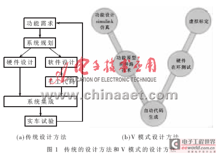
As shown in Figure 1, compared with traditional design methods, the V-mode design method applies the principles of system engineering to the development of modern automotive electronic systems. It is a cyclical design model. Its characteristics are that no matter whether it is development, programming or testing, it is always working in the same environment, and each step of the development process can be verified [1]. It is based on powerful computing simulation tools. The entire design process is completed on the same platform, realizing seamless connection from the proposal of design concepts to rapid prototyping (Prototype) and then to ECU products. The most direct effect of adopting this method is to accelerate and simplify the development process, eliminate errors in a timely manner, and greatly reduce the workload of engineers.
1.2 Automatic code generation using Simulink
Automatic code generation is at the bottom of the V model and is the most critical step in the entire development process. Its purpose is to achieve rapid iteration during the development process to improve development efficiency. The quality of code generation directly affects the reliability and stability of the system.
Figure 2 shows the DSP automatic code generation process based on MATLAB/Simulink [2]. Simulink is a platform for multi-domain simulation and model-based design of dynamic systems. It provides an interactive graphical environment and a rich module library. According to the functional requirements of the system, the system model is first built in the MATLAB/Simulink environment and simulation analysis is performed. The Simulink debugger is used to check the simulation results and locate and diagnose unexpected behaviors in the model. Once the results are verified, the C language project files for the TI compiler can be automatically generated through RTW (Real-time workshop), and further compilation, connection and download are completed, and finally run on the hardware platform.
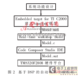
RTW is a tool used with MATLAB and Simulink. It can generate code directly from Simulink models and automatically build programs that can run in real time. By default, RTW generates highly optimized and fully annotated C code. In addition to MATLAB function modules and modules that call M-file S functions, any Simulink model can generate code, including linear, nonlinear, continuous, discrete, and hybrid models [3].
From the whole process, engineers only need to build models in Simulink and verify the correctness of the models without writing any code to obtain reliable and accurate code.
2 Embedded Target for TI C2000 Toolbox
Target for TI C2000 integrates TI's eXpressDSP tool into Simulink, which is a connection tool between MATLAB and TI CCS, enabling MATLAB, MATLAB toolbox, TI Code Composer Studio integrated development environment (CCS IDE) and RTDX (Real-Time Data Exchange) to work together.
The Target for TI C2000 toolbox consists of three parts [3]: common tools, chip peripheral module library, and optimization library. Common tools include real-time data exchange channel module, target controller basic parameter setting module, and CAN communication setting module. The toolbox supports DSPs of the C281x series, C280x series, and C2400 series. The optimization library includes a fixed-point operation library and a digital motor control library.
Simulink can support four types of C280x DSP peripheral module libraries: memory read and write modules, interrupt management modules, control modules, and communication modules. Except for not supporting IIC communication modules, this module library provides good support for all modules on the C280x DSP board. When users call these modules of DSP, they only need to set and select the corresponding modules, and do not need to care about how the underlying layer is implemented. The entire model building process is as simple as stacking blocks.
3 Application of Automatic Code Generation in Battery Management System
3.1 Functional Description of Battery Management System
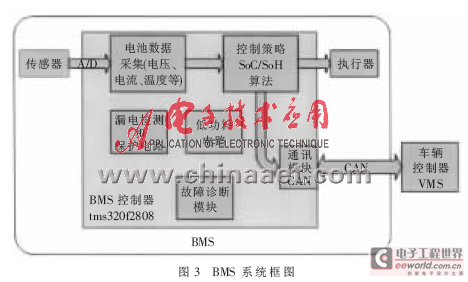
BMS The lithium-ion battery management system (BMS) for fuel cell vehicles is an embedded real-time monitoring system that should have the following functions [4]: battery status monitoring, including measurement and signal processing of battery operating voltage, operating current and operating temperature; calculation of maximum charge and discharge power under specific conditions; estimation of battery pack state of charge (SoC) and life state (SoH) under specific working conditions; high-voltage pre-charging, overcharge and over-discharge protection, insulation detection and leakage protection; battery balancing and thermal management; fault diagnosis and communication with the vehicle controller. Figure 3 is a block diagram of the BMS system.
Since the BMS still needs to monitor the battery at regular intervals when the car is parked, the BMS cannot use up all the power stored in the battery when the car is parked for a long time, otherwise the car will not be able to start. Therefore, when the car is parked, the BMS must enter the low power mode. When the car starts, the ignition signal from KL15 wakes up the controller from the low power mode and enters the normal working mode.
3.2 Controller Selection
From the functions of BMS, it can be seen that the control function of the controller only accounts for a small part of BMS. In real-time parameter estimation and SoC estimation, the algorithm is complex and the amount of calculation is large. The controller needs to complete complex recursive calculations in a short time interval, which requires higher computing power and speed of the controller. The traditional battery management system uses a single-chip microcomputer as a controller. Since the single-chip microcomputer focuses on control and has limited real-time data computing capabilities, it cannot meet the requirements of BMS well. TI's TMS320C2000 series DSP combines the characteristics of microcontrollers and high-performance DSPs, has powerful control and signal processing capabilities, and can implement complex control algorithms. This series of DSPs integrates Flash memory, fast and high-precision A/D converters, two-way enhanced CAN modules, event managers, orthogonal encoding circuit interfaces, multi-channel buffered serial ports and other peripherals. The 32-bit fixed-point C2808 DSP can complete 32×32-bit multiplication and accumulation operations or two 16×16-bit multiplication and accumulation operations in one cycle. In addition, any memory address can be read, modified, and written within one cycle, achieving optimal efficiency and program code, fully meeting the requirements of real-time control [5].
3.3 Battery Parameter Identification and SoC Estimation Algorithm
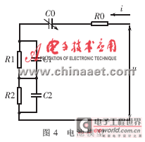
Battery monitoring must first be modeled to detect the battery voltage, current and temperature in real time. The model parameters are identified based on these data, thereby indirectly estimating the internal conditions of the battery. Figure 4 shows a lithium-ion power battery model [6]. In the model, C0 is used to describe the battery capacity, R0 is used to describe the equivalent ohmic internal resistance of the battery, R1 and C1 with smaller time constants are used to describe the impedance of lithium ions when they are transmitted between electrodes, and R2 and C2 with larger time constants are used to describe the impedance of lithium ions when they diffuse in the electrode material. The parameters in this model can all be obtained through parameter identification methods.
In order to achieve adaptive control and track parameters that change over time, a recursive least squares method is used in the identification process. The internal parameters of the battery are updated according to the sampled values of the voltage and current signals each time. The basic idea is that the estimated value this time is equal to the estimated value of the previous time plus a correction term, and the size of the correction term depends on the difference between the model output and the actual output. This method requires that a recursive operation must be completed before the next sampling.
When the vehicle is installed and running, the vehicle controller needs the BMS to provide a high-precision SoC, and the general estimated accuracy is less than 5%. The battery SoC cannot be obtained directly, but can only be indirectly estimated by measuring battery voltage, current, temperature, internal resistance and other parameters. Moreover, these parameters are related to the degree of battery aging, the non-uniformity of battery cells, etc. At present, common methods include open circuit voltage method, current integration method, etc.
3.4 Calibration module based on CAN bus
Due to the widespread use of network systems in automobiles, the calibration of control units based on network connections is very different from the traditional matching calibration method. The calibration of CAN-based electronic control units is an important part of the development of battery management system controllers. CCP (CAN Cali-bration Protocol) is a calibration protocol for the CAN bus, which has been widely used by automobile manufacturers. The protocol can be used to calibrate the controller quickly and effectively. In the battery management system, CCP can be used to achieve real-time online testing, sensor monitoring and calibration, adjustment of alarm or error thresholds, and program downloading via CAN.
In the traditional controller design process of hand-written code, calibration based on CCP protocol requires a driver that supports CCP protocol. Since the ECU underlying program and the driver of CCP protocol are different, it takes a lot of time to integrate CCP driver into ECU. MATLAB 2007b adds a calibration module based on CAN bus. By putting this module into Simulink model and setting relevant parameters, the code that can realize CCP calibration can be automatically generated.
3.5 Building a Model in Simulink
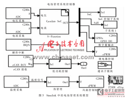
At the beginning of modeling, the F2808 eZdsp module in the C2000 DSP chip support must be placed in the model. This module sets the basic information of the DSP, including chip selection, phase-locked loop clock frequency selection, memory address allocation, and some basic settings of peripheral devices.
The sensor outputs analog signals and digital signals. The analog signal can be converted by the A/D conversion module, and the digital signal can be processed by the GPIO or CAP capture module. The analog sampling signal after hardware filtering is not ideal. In this model, the sampling signal can be fast Fourier transformed to analyze the frequency characteristics of the noise signal, and the corresponding digital filter can be designed to further filter the sampling signal. The actuator can be controlled by the GPIO or PWM module.
Since SoC, SoH and control algorithms are relatively complex, they can be implemented using S-function modules. S-function is a computer language description of a dynamic system and a powerful tool for expanding the Simulink module library. It uses a specific calling syntax to implement the interaction between functions and Simulink solvers. The battery management system model in Simulink is shown in Figure 5.
3.6 Automatic code generation, compilation and execution
After the simulation runs correctly in Simulink, the control algorithm code can be directly generated from the model. Simulink calls the real-time workshop build internally and automatically opens TI's integrated development environment CCS. The generated code is compiled and automatically generates an executable final control program. The program is burned into the target system through the USB interface simulator and the 14-pin standard JTAG debugging cable.
C2808 DSP has two operation modes. One is to download the program to RAM through the emulator and run it. In this operation mode, you can set breakpoints, single-step operation, and view memory in CCS through the emulator to monitor and debug the program in real time. The other mode is to download the program to Flash and run it separately. This operation mode does not require the intervention of CCS. Generally, the RAM mode is used in the experimental debugging stage, and the Flash mode is used to run it separately after the debugging is successful.
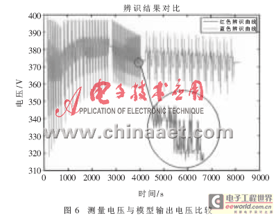
The designed controller is used for current and voltage sampling, with a voltage sampling accuracy of 1/1000 and a current sampling accuracy of less than 5/1000. The designed SoC algorithm can complete a one-step recursive operation on the DSP within 30ms, meeting the requirements of real-time operation of the battery management system. Running the automatically generated code and combining with Vector's CANape tool successfully implements the CCP protocol for online calibration of parameters in RAM and Flash memory. Figure 6 is a comparison of the measured voltage and the model output voltage. As can be seen from the figure, the measured voltage is quite consistent with the model output voltage, confirming the correctness of the code.
Practice shows that the application of DSP to replace the traditional single-chip microcomputer as the controller of BMS, its powerful control ability and signal processing ability can better meet the requirements of battery management system. The automatic code generation of the controller is realized by using the embedded Target for TI C2000 under the Matlab/Smulink platform, which greatly accelerates the development process of the electric vehicle BMS system and shortens the development cycle. The operation test shows that the automatically generated code is efficient and reliable, the controller's control effect on the battery system is real-time and accurate, and the reliability is high. The parameter estimation of the battery model meets the accuracy requirements.
Previous article:A DSP-based fuzzy PID control of inverter power supply
Next article:Design and implementation of digital phase shifter-voltage converter module based on DSP
Recommended ReadingLatest update time:2024-11-16 14:32


- Popular Resources
- Popular amplifiers
- Huawei's Strategic Department Director Gai Gang: The cumulative installed base of open source Euler operating system exceeds 10 million sets
- Analysis of the application of several common contact parts in high-voltage connectors of new energy vehicles
- Wiring harness durability test and contact voltage drop test method
- Sn-doped CuO nanostructure-based ethanol gas sensor for real-time drunk driving detection in vehicles
- Design considerations for automotive battery wiring harness
- Do you know all the various motors commonly used in automotive electronics?
- What are the functions of the Internet of Vehicles? What are the uses and benefits of the Internet of Vehicles?
- Power Inverter - A critical safety system for electric vehicles
- Analysis of the information security mechanism of AUTOSAR, the automotive embedded software framework
 Professor at Beihang University, dedicated to promoting microcontrollers and embedded systems for over 20 years.
- Innolux's intelligent steer-by-wire solution makes cars smarter and safer
- 8051 MCU - Parity Check
- How to efficiently balance the sensitivity of tactile sensing interfaces
- What should I do if the servo motor shakes? What causes the servo motor to shake quickly?
- 【Brushless Motor】Analysis of three-phase BLDC motor and sharing of two popular development boards
- Midea Industrial Technology's subsidiaries Clou Electronics and Hekang New Energy jointly appeared at the Munich Battery Energy Storage Exhibition and Solar Energy Exhibition
- Guoxin Sichen | Application of ferroelectric memory PB85RS2MC in power battery management, with a capacity of 2M
- Analysis of common faults of frequency converter
- In a head-on competition with Qualcomm, what kind of cockpit products has Intel come up with?
- Dalian Rongke's all-vanadium liquid flow battery energy storage equipment industrialization project has entered the sprint stage before production
- Allegro MicroSystems Introduces Advanced Magnetic and Inductive Position Sensing Solutions at Electronica 2024
- Car key in the left hand, liveness detection radar in the right hand, UWB is imperative for cars!
- After a decade of rapid development, domestic CIS has entered the market
- Aegis Dagger Battery + Thor EM-i Super Hybrid, Geely New Energy has thrown out two "king bombs"
- A brief discussion on functional safety - fault, error, and failure
- In the smart car 2.0 cycle, these core industry chains are facing major opportunities!
- The United States and Japan are developing new batteries. CATL faces challenges? How should China's new energy battery industry respond?
- Murata launches high-precision 6-axis inertial sensor for automobiles
- Ford patents pre-charge alarm to help save costs and respond to emergencies
- New real-time microcontroller system from Texas Instruments enables smarter processing in automotive and industrial applications
- TGF4042 Function Signal Generator Review: Unboxing and Trial
- 【McQueen Trial】Python Programming (3)
- [Reprint] Summary of Zynq7010 NAND startup
- Free sharing of LDO and DCDC basic principle explanation video
- No response when controlling GPIO in user mode?
- Logistics POS machine with serial port expansion IC
- EEWORLD University Hall----Live Replay: Infineon system solutions make electric motorcycle design more reliable and efficient!
- EEWORLD University Hall----Live Replay: ADI's smoke detector integrated solution based on ADPD188BI
- How to use 4G base stations and 5G base stations in rural areas
- EEWORLD University Hall----Live Replay: Fujitsu Empowers Automotive Electronics Technology Transformation

 MATLAB and FPGA implementation of wireless communication


 京公网安备 11010802033920号