1 System Description
A tire pressure monitoring sensor is installed inside each wheel, which can accurately measure the pressure and temperature inside the tire. The sensor sends the tire pressure and temperature values to the body control model (BCM) wirelessly according to a certain rule. The BCM sends the information frame to the dashboard through the CAN bus, and the driver obtains the pressure and temperature values of each tire through the dashboard display. When the pressure or temperature value of a tire changes beyond the alarm value, the dashboard can accurately display the position of the alarm tire and issue graphic, sound, and text alarms. At the same time, the low-frequency antenna installed at the position of each tire fender communicates with the BCM, and parses and converts the operation information required by the BCM into 125 kHz low-frequency wireless data for transmission. The tire pressure monitoring sensor will receive this low-frequency wireless signal and then work according to the parsed operation information. The above is the TPMS two-way communication system. Since this product is a safety component of an automobile product, it should have high reliability in various environments, including: various weather conditions, such as cloudy days, rainy days, etc.; various road conditions, such as national highways, expressways, rural roads, mountain roads, etc.; snowy roads, ice surfaces, and extremely cold areas (-40°C) in winter; hot and humid areas in summer (surface temperature +50°C, 90% humidity); different vehicle speeds (0-200 km/h), etc. This requires strict selection of various components when designing automobile tire pressure monitoring sensors.
2 Circuit Design
Since the automobile tire pressure monitoring sensor is installed inside the tire and has no contact with the outside world, it requires not to be maintained and repaired too frequently. It is generally required to have a service life of 10 years, and its operating temperature range is -40 to +125°C. This requires that the selected devices must be automotive-grade and low-power components.
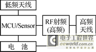
Figure 1 System composition block diagram
The block diagram of the automobile tire pressure monitoring sensor system is shown in Figure 1.
2.1 Sensor Selection
MCU/Sensor is the core of the system, which is implemented by Infineon's SP300V2.1E1060. SP300V2.1E1060 integrates silicon micro-machined pressure sensor, temperature sensor and acceleration sensor and a battery voltage monitor, and integrates a low-power 8-bit Harvard structure RISC controller; it has four working modes: power off, run, idle, and shutdown, and three wake-up methods: IT/LT wake-up, PORT wake-up and LF low-frequency detection wake-up, which can effectively meet the system's low-power design requirements. The pressure measurement range is 0~3.5 Bar; the temperature measurement range is -40~+125 ℃; the centripetal acceleration measurement range is -12g~115g; the operating voltage range is 1.8~3.6 V.
2.2 RF unit selection
RF radio frequency chips are mainly used to convert digital signals into high-frequency signals. The system uses Maxim's MAX7044 chip, which has an operating voltage of +2.1~+6.0 V, a low operating current of 8 mA, OOK/ASK modulation, a communication rate of up to 100 kbps, and a small package of 3 mm×3 mm, 8-pin SOT23 package. It eliminates the problems of SAW transmitter design; adopts a crystal structure, provides a greater modulation depth and a fast frequency response mechanism; reduces the influence of temperature, and the temperature range can reach -40~+125℃. It contains power amplifier (PA), crystal oscillator, driver, data activity detector, lock detection circuit, phase-locked loop (32x PLL), divider (16 divider) and other circuits.
MAX7044 has an automatic low power mode (shutdown mode) control method. If the DATA pin does not move within a certain time (wait time), the device automatically enters low power mode. The waiting time is about 216 clock cycles, which is about 4.84 ms at 433 MHz. The waiting time to enter low-power mode is: tWAIT=216×32fRF. Where fRF is the RF transmission frequency. When the device is in low-power mode, the crystal oscillator and PLL are "hot" started at the rising edge of the DATA signal. The crystal oscillator and PLL require 220 μs of settling time before data transmission. The relationship between the reference frequency and the carrier frequency is: fXTAL=fRF/32.
The main characteristic parameters of the MAX7044 are as follows:
- +2.1~+3.6 V single power supply
- OOK/ASK transmission data format
- Maximum data rate 100 kbps
- +13 dBm output power (50 Ω load)
- Low supply current (7.7 mA typical)
- 250 μs fast start-up time
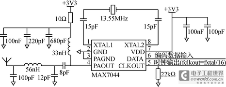
The transmitting circuit diagram composed of MAX7044 is shown in Figure 2. In actual design, according to the actual impedance of the antenna and the input impedance of the RF transmitting chip, a π-type matching network is used to complete the impedance matching between the RF transmitting chip and the antenna to achieve maximum power output.
Figure 2 MAX7044 circuit diagram
2.3 Battery Selection
The battery selected is the high temperature series battery (TLH) launched by Israel's Tadiran Battery Company, with a supply voltage of +3.6 V and a battery capacity of 500 mAh. It has the characteristics of long life, high energy density, extremely low self-discharge, light weight (8.8 g), and wide temperature range (-55 ~ +125 ℃).
2.4 Low-frequency interface and calculation
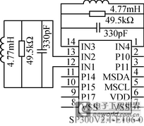
In LF low-frequency communication, SP300V2.1E1060 receives low-frequency information from BCM. The low-frequency antenna consists of a resistor, capacitor and inductor in parallel,
as shown in Figure 3. In order to achieve the optimal low-frequency receiving sensitivity, the resonant frequency of the inductor and capacitor is designed to be a low-frequency carrier frequency of 125 kHz. The resonant frequency calculation formula is fc=(2πLC)-1. The low-frequency inductor uses Premo's TP11030477, with an inductance of 4.77 mH. The capacitance value is calculated by the above formula:
Figure 3 Schematic diagram of low-frequency hardware circuit
The parallel resistor R mainly reduces the quality factor Q (Quality Factor) value of the LCD resonant circuit to achieve sufficient low-frequency bandwidth (7.8 kHz). The quality factor Q of the resonant circuit = fcBW = 125 kHz2 × 3.9 kHz = 15, which requires that the quality factor Q of the LF resonant circuit cannot be greater than 15. The resistance R can be calculated as Q × XL = 15 × 2π × fc × L = 49.5 kΩ.
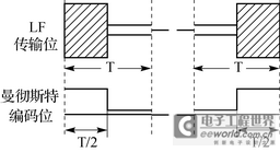
Since the SP300V2.1E1060 low frequency wake-up and receiving baud rate hardware is set to 3.9 kbps Manchester encoding, Figure 4 shows the relationship between low frequency carrier data transmission and Manchester encoding.
Figure 4 Relationship between Manchester coding and LF carrier transmission
Since the hardware has been fixed to 3.9 kbps Manchester code baud rate, the time of each LF transmission bit is calculated to be 3.9 kbps×2=7.8 kbps.
3 Antenna Design
The performance of the antenna will directly affect the quality of data transmission, and it is an important factor in improving the transmission power of the automobile tire monitoring sensor. The antenna of the automobile tire monitoring sensor is close to the valve nozzle. Therefore, when designing the antenna, it is necessary to consider the shielding of the tire wire, the reflection of the rim metal, and the influence of the antenna constantly changing direction and angle when the wheel rotates at high speed. Therefore, the following factors must be considered when designing the antenna: polarization selection, linear polarization is easily affected by the antenna posture, and the rotating wheel has relatively high requirements for the working polarization of the antenna; the antenna is connected to the RF module, and the impedance matching problem needs to be solved, which is also the focus of the antenna design; since the tire pressure sensor is installed in the tire, it is affected by the body and antenna movement, mainly referring to the gain, directional pattern shape, impedance (resistance and reactance) of the antenna; miniaturization design, the antenna installed inside the tire must consider miniaturization design, the working frequency is 433.92 MHz, the wavelength is 691.37 mm, and the conventional antenna size must not meet the requirements.
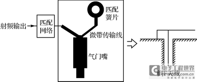
Based on the above considerations, the valve nozzle is selected as the antenna of the transmitting module. This antenna has the advantages of easy processing, low cost, easy integrated design, and easy matching.
The valve antenna is a commonly used antenna form for automobile tire monitoring sensors at home and abroad. It belongs to the category of small electric antennas. The design focus of small electric antennas is on the design of structural dimensions and the setting of matching circuits. Because the radiation resistance of small electric antennas is generally small (a few Ω), the radiation efficiency of small electric antennas is generally low, and there is often an imaginary part in the radiation impedance. This energy storage factor will further reduce the radiation efficiency. The imaginary part can be solved by a matching circuit, but the real resistance needs to be matched with the impedance of the RF output pin of the transmitting chip, which is also the design focus of the transmitting small electric antenna. The antenna loading method adopted in this scheme is loaded by an internal matching brass sheet, which is similar to the inverted F antenna loading method, as shown in Figure 5. After bench tests and road tests, it is shown that our design ideas and matching methods are effective.
Figure 5 Schematic diagram of valve antenna and equivalent inverted F antenna
4 Software Design
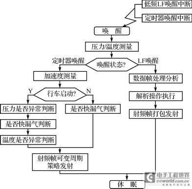
The system has the following software functions: periodic measurement of tire pressure and temperature values, variable periodic transmission of tire pressure and temperature values, BCM low-frequency RF data reception and processing, high air pressure alarm function, low air pressure alarm function, high temperature alarm function, fast air leakage alarm function, low battery voltage alarm function, sensor no signal alarm function. The system is required to have a 10-year long life. To achieve such a long service life, the system is in a dormant state under normal conditions, with a static current of only 0.6 μA. The system can be awakened from the dormant state through a low-frequency LF interrupt or a timer interrupt. The system software framework flow is shown in Figure 6.
Figure 6 System software framework flow chart
The internal ROM of SP300V2.1E1060 comes with a low-level library function (Library Function), and users can directly call the library function.
Since the tire pressure sensor installed inside each tire on the car may transmit high-frequency data at the same time, radio frequency interference will occur between the data during this period, resulting in the failure of the BCM controller radio frequency receiving end to receive the correct data, that is, data conflict. Data conflict is generated randomly and cannot be avoided, but the probability of data conflict occurring again after the conflict occurs must be as low as possible to avoid continuous data conflicts. At present, the system adopts a random delay between each high-frequency data frame transmission. The random delay time is a prime number multiple of the data frame time length. The system selects 3 times, 5 times, 7 times, 11 times and 13 times. In this way, if there is a data conflict in the previous module, the data conflict will only occur again when the random delay time of the module sending the conflict is the same, and the probability is 4%.
5 Structural Design
The tire pressure sensor is installed inside the tire of the car and consists of a valve, a shell and a dust cap. The maximum speed of a car can reach 250 km/h, and the internal environment of the tire is complex and extremely harsh. It is exposed to high pressure, high humidity, temperature alternation, oil pollution, bumps and vibrations for a long time. The temperature changes can easily make the shell brittle and reduce the mechanical strength. High humidity can also cause the shell to expand, reduce strength and produce chemical reactions such as corrosion. The tires are driven on 21 types of roads, and the frequency and amplitude of bumps and vibrations are different. These situations may cause the parts to loosen. This requires the system structure design to consider the following points: the total weight of the system is required to be light (less than 40 g), high speed rotation acceleration performance, high structural fracture strength, high sealing (IP6 protection level), high and low temperature resistant and corrosion resistant materials are selected for the structure and valve materials, and the valve and rim joints have anti-loosening design.
6 Conclusion
Whether it is a bench test or a road test in various situations, the tire pressure sensor maintains high reliability, and the system low-frequency transmission and reception accuracy and high-frequency transmission and reception accuracy reach 98%. When the tire is in an abnormal and dangerous situation, the car dashboard will display relevant alarm information to remind the driver in real time, thus eliminating accidents caused by tire pressure problems in the bud and enhancing the safety of car driving.
Previous article:Analysis of electromagnetic suspension technology for 500,000 yuan mid-range cars
Next article:Research and solutions for automotive electric power steering systems
- Popular Resources
- Popular amplifiers
- 2024 China Automotive Charging and Battery Swapping Ecosystem Conference held in Taiyuan
- State-owned enterprises team up to invest in solid-state battery giant
- The evolution of electronic and electrical architecture is accelerating
- The first! National Automotive Chip Quality Inspection Center established
- BYD releases self-developed automotive chip using 4nm process, with a running score of up to 1.15 million
- GEODNET launches GEO-PULSE, a car GPS navigation device
- Should Chinese car companies develop their own high-computing chips?
- Infineon and Siemens combine embedded automotive software platform with microcontrollers to provide the necessary functions for next-generation SDVs
- Continental launches invisible biometric sensor display to monitor passengers' vital signs
- Intel promotes AI with multi-dimensional efforts in technology, application, and ecology
- ChinaJoy Qualcomm Snapdragon Theme Pavilion takes you to experience the new changes in digital entertainment in the 5G era
- Infineon's latest generation IGBT technology platform enables precise control of speed and position
- Two test methods for LED lighting life
- Don't Let Lightning Induced Surges Scare You
- Application of brushless motor controller ML4425/4426
- Easy identification of LED power supply quality
- World's first integrated photovoltaic solar system completed in Israel
- Sliding window mean filter for avr microcontroller AD conversion
- What does call mean in the detailed explanation of ABB robot programming instructions?
- 2024 China Automotive Charging and Battery Swapping Ecosystem Conference held in Taiyuan
- State-owned enterprises team up to invest in solid-state battery giant
- The evolution of electronic and electrical architecture is accelerating
- The first! National Automotive Chip Quality Inspection Center established
- BYD releases self-developed automotive chip using 4nm process, with a running score of up to 1.15 million
- GEODNET launches GEO-PULSE, a car GPS navigation device
- Should Chinese car companies develop their own high-computing chips?
- Infineon and Siemens combine embedded automotive software platform with microcontrollers to provide the necessary functions for next-generation SDVs
- Continental launches invisible biometric sensor display to monitor passengers' vital signs
- Another technical solution for power-type plug-in hybrid: A brief discussion on Volvo T8 plug-in hybrid technology
- ZTXZTX talks about lead-acid battery maintenance
- RISC-V MCU Development (XII): Command Line Operations
- [Qinheng RISC-V core CH582] CH582 wired keyboard to Bluetooth keyboard
- GD32 pin PWM output stops level issue
- What's wrong with this circuit?
- Are audio amplifiers, Class A, Class B, Class C, Class AB, Class D, OTL, etc. circuits a type of DAC amplification? And...
- Analysis of the application of smart antenna technology MIMO in wide area wireless networks
- [N32L43x Review] 8. Flash read\write\erase - using internal Flash to store data
- EMC (Electromagnetic Compatibility) Design
- EMC Design of RS-485 Port

 TS635IDWT


 京公网安备 11010802033920号