ADAS1000 ECG front end with integrated respiration and pulse detection
ADP151 Ultralow Noise, 200 mA CMOS Linear Regulator
Evaluation and Design Support
Circuit Evaluation Board
Evaluation board (EVAL-ADAS1000SDZ)
System Demonstration Platform (EVAL-SDP-CB1Z)
Design and Integration Documentation
Schematics, layout files, bill of materials
Circuit Function and Advantages
This circuit is a highly integrated electrocardiogram (ECG) front end for battery-powered patient monitoring applications. Figure 1 shows a top-level block diagram of the physical connections of a typical 5-lead (4 limb leads and 1 precordial chest lead) ECG measurement system with integrated respiration and pulse detection. This configuration is typically used for portable telemetry ECG measurements or as a minimum lead setup for line-powered bedside instruments.
When measured on the skin surface, the ECG signal amplitude is small, typically 1 mV. Important information about the patient's health and other parameters is contained in that small signal, so the device requires measurement sensitivity in the μV level. On the system side, many medical standards require a maximum noise of no more than 30 μV pp; however, designers often set this value lower. Therefore, all noise sources must be considered when designing a solution that meets system-level requirements.
The noise performance of the ADAS1000 is specified for a variety of different operating environments. The power supply must be designed to ensure that it does not degrade the overall performance. The ADP151 linear regulator was chosen due to its ultralow noise performance (9 μV rms typical, 10 Hz to 100 kHz), which combined with the power supply rejection performance of the ADAS1000 ensures that the noise generated by the ADP151 does not affect the overall noise performance.
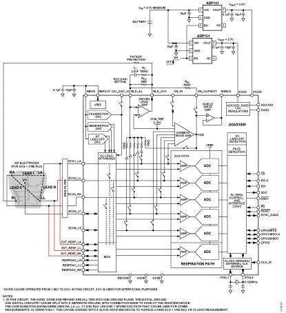
Figure 1. Simplified ADAS1000 functional block diagram for a typical 4-electrode + RLD or 5-lead configuration (all connections and decoupling not shown)
Circuit Description
The ADAS1000 five-electrode ECG analog front end (AFE) addresses the challenges of a new generation of low power, low noise, high performance tethered and portable ECG systems.
The ADAS1000 is a highly integrated chip consisting of five electrode inputs and a dedicated right leg drive (RLD) output reference electrode designed for monitoring and diagnostic grade ECG measurements.
In addition to supporting the basic elements for monitoring ECG signals, the ADAS1000 is also equipped with functions such as respiration measurement (thoracic impedance measurement), pacing artifact detection, lead/electrode connection status, and internal calibration.
A single ADAS1000 supports 5 electrode inputs, making it easy to perform traditional 6-lead ECG measurements. Connecting a second ADAS1000 slave device in parallel adjusts the system to a true 12-lead measurement (consisting of 9 electrodes and 1 RLD), and adding multiple slave devices (3 or more) adjusts the system to 15-lead measurements or even more.
The ADAS1000 integrates a digital-to-analog converter (DAC) for respiration drive at a programmable frequency of 46 kHz to 64 kHz, and an analog-to-digital converter (ADC) to simplify this complex measurement process. The measured signal is demodulated and converted into amplitude and phase information, from which the corresponding respiration information can be determined, thereby obtaining specific cable parameters. This circuit has a resolution of 200 mΩ when using internal capacitors and a higher resolution (<200 mΩ) when using external capacitors. The circuit has a flexible switching scheme that allows measurement of one of the three leads (I, II, or III).
PACE DETECTION ALGORITHM The pace detection algorithm runs three instances of a digital algorithm on three of the four possible leads (I, II, III, or aVF). It runs on the high frequency ECG data in parallel with internal decimation and filtering. The algorithm is designed to detect and measure pacing artifacts with widths ranging from 100 μs to 2 ms and amplitudes from 400 μV to 1000 mV. The ADAS1000 returns a flag to indicate whether a pace signal was detected on one or more leads, along with the height and width of the detected signal. When the user wishes to run their own digital pace algorithm, the ADAS1000 provides a high speed pace interface that provides ECG data at a very fast data rate (128 kHz), while the filtered and decimated ECG data on the standard interface remains unchanged.
The low-power ADAS1000 is designed for low power consumption, requiring only 21 mW to measure five ECG electrodes. To further reduce overall power consumption in applications such as battery-powered Holter and telemetry, all unused channels and features can be easily disabled to further reduce power consumption of a single ECG lead to 11 mW.
Low noise
Low noise performance is critical for proper diagnosis under different conditions. End equipment needs to rely on the noise performance of the ADAS1000 to meet regulatory standards. The ADAS1000 allows for trade-offs between noise performance, power consumption, and data rate, making it suitable for use in a variety of products. The ADAS1000 also performs very well in line-powered ECG systems where power consumption is not a major concern.
The noise performance of the device can be optimized by using its high-performance mode, in which the sampling rate of the on-chip SAR ADC increases to 2 MSPS, thereby achieving a higher signal-to-noise ratio (SNR).
Flexible data rate
A standard serial interface outputs all ECG related information including lead-off status, pacing, respiration and other auxiliary functions. A number of 32-bit or 16-bit data words, collectively called "packets" or "frames", are output via the serial SDO pin of the data bus. Different data frame rates (2 kHz, 16 kHz or 128 kHz) are available, ensuring ultimate simplification of the data acquisition task. The lowest data rate (2 kHz) allows for more decimation capabilities and optimizes the frame data rate for low noise performance. Data can also be read in skip mode, which reads a packet or frame from the device every second or third word. The minimum data rate is 500 Hz.
A photo of the ADAS1000 evaluation board connected to the SDP board is shown in Figure 2.
The EV kit is designed to provide 1-lead to 12-lead ECG measurements.
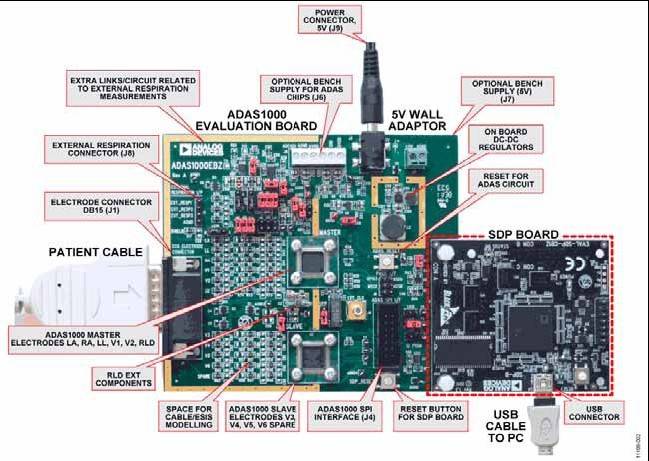
Figure 2. ADAS1000 Evaluation Board/SDP Board (EVAL-SDP-CB1Z)
Batteries for portable ECG applications
Batteries used in portable ECG devices vary, and in some cases may use AA or AAA batteries, which are easy to replace or recharge.
Batteries add to the overall weight of the instrument. Since patient comfort is very important, reducing the size and weight of the overall solution while maintaining battery life is a top consideration in portable ECG applications.
The latest products tend to use battery chemistries such as lithium-ion and can provide power from a few hours to a few days, depending on the product.
The battery voltage range depends on the supply range of the components in the system. The ADAS1000 requires an AVDD of 3.3 V. Therefore, if the ADP151 regulator is used, the battery must supply at least 3.7 V, with a required margin of 400 mV. The nominal voltage of a lithium-ion or lithium-polymer battery is 3.7 V; however, the discharge voltage is approximately 3.2 V. Therefore, two stacks are required to ensure that the ADP151 reaches the minimum voltage of 3.7 V.
Choosing the Right Power Solution The ADAS1000 requires at least two power rails—AVDD and IOVDD. As shown in Table 1, the ADCVDD and DVDD rails are optional; using the ADAS1000's integrated on-chip LDO, power can be obtained from the AVDD or IOVDD rails, respectively.
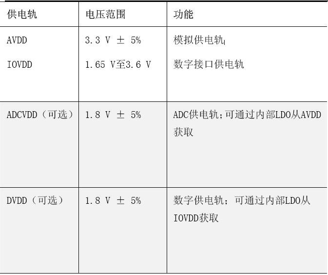
Table 1. Power Supplies Required for the ADAS1000
AVDD and IOVDD are powered by a 3.3 V supply on the evaluation board. 3.3 V was chosen for the IOVDD supply rail to maintain compatibility with the SPORT interface on the EVAL-SDP-CB1Z. The IOVDD supply voltage can be as low as 1.65 V if interfacing with a microcontroller operating at a lower supply voltage is required.
Alternatively, if a more power efficient solution is desired, the ADCVDD and DVDD internal rails can be disabled via hardware pins (VREG_EN) on the ADAS1000 so that the ADCVDD and DVDD rails can be driven externally. Since the ADCVDD rail powers the ADC on-chip, it must be kept as clean as possible and must not be used with noisy digital supplies.
The AVDD rail supply current to power a single ADAS1000 is typically between 8 mA and 15 mA, depending on the mode of operation, with all five channels enabled; inactive channels can be disabled to reduce power consumption.
A dedicated ADP151 serves both the AVDD and IOVDD supplies on the evaluation board. Note that each ADP151 can drive 200 mA and can therefore power other components within the system. The input to the ADP151 regulator is from a 5 V rail that is used elsewhere on the board.
With proper filtering, a single ADP151 can provide power to both the AVDD and IOVDD rails, ensuring that the AVDD rail is not affected by any digital noise on the IOVDD rail.
The EVAL-ADAS1000SDZ evaluation board is designed to provide the required 5 V power to the EVAL-SDP-CB1Z board at approximately 250 mA. The ADP2503 buck-boost dc-to-dc converter generates the 5 V rail from the 4.5 V to 5.5 V input supply connected to the board.
If this hardware is connected to an SDP board and powered by a battery, the total power consumption will quickly drain the battery.
Common changes
Other pin-compatible ECG front ends in the ADAS1000 family offer fewer features. For example, the ADAS1000-4 is a 3-channel version with pulse and respiration detection, and the ADAS1000-3 offers 3 ECG channels without pulse or respiration detection. The ADAS1000-2 is a companion device with 5 ECG channels for combined configuration mode, supporting 12-lead ECG measurements (9 ECG electrodes and 1 RLD). Table 2 lists the differences between the products in this family. These product families ensure flexible configurations that can be expanded from a small number of leads all the way to 15-lead measurements, or even more.
A DC-DC converter can be used for the power supply to achieve higher efficiency, but careful layout and avoidance of ripple noise are required.
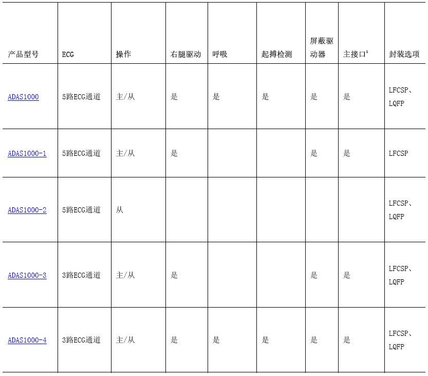
Table 2. Overview of the features of the different members of the ADAS1000 family.
A master interface is provided for users who wish to use their own digital pacing algorithm; see the Second Serial Interface section in the ADAS1000 data sheet.
Circuit Evaluation and Testing
Equipment List
The following equipment is needed:
EVAL-ADAS1000SDZ kit, including the EVALADAS1000SDZ evaluation board, 5 V wall power supply, and CD containing the ADAS1000 evaluation software
EVAL-SDP-CB1Z system demonstration board
A PC with an integrated USB port and the ADAS1000 evaluation software installed
Patient simulator or function generator for signal capture
For detailed instructions on how to use the ADAS1000 evaluation board, refer to the ADAS1000SDZ User Guide. Figure 3 shows a typical screen shot using the evaluation board software with the evaluation board connected to a patient simulator.
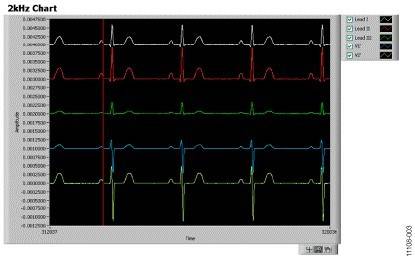
Figure 3. Screen shot of the ADAS1000 connected to the patient simulator, heart rate = 70 BPM.
The noise measurement evaluation board software was used to capture the peak-to-peak noise performance of the ECG lead path using the ADAS1000 evaluation board. The results are shown in Figure 4. The device configuration conditions were as follows:
Gain set to 1.4
ADC sampling rate is 2 MSPS (high performance mode)
Data rate 2 kHz
Configuration in digital lead mode (digital calculated leads)
ECG channels connected to 1.3 V internal test tone
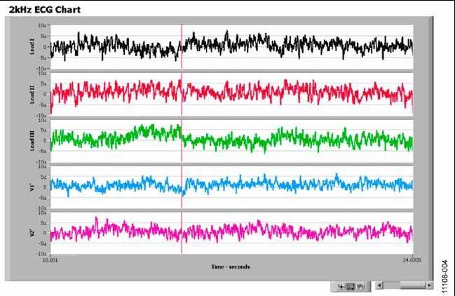
Figure 4. Screen shot of ADAS1000 noise measurement in leads mode using the ADAS1000 evaluation board and evaluation software.
The x-axis represents time, showing the signal capture over a few seconds, and the y-axis, in μV, represents the noise performance under these conditions for a signal variation of ±7 μV. This is consistent with the expected ADAS1000 performance and is comparable to the performance on the same hardware when using a low noise linear bench supply. It demonstrates that the ADP151 power supply circuit on the evaluation board does not result in a significant increase in the overall noise of the ADAS1000.
Conditions for using this evaluation board and circuit note
Refer to the ADAS1000SDZ User Guide for the complete disclaimer.
THIS EVALUATION BOARD DESIGN IS PROVIDED "AS IS" WITHOUT WARRANTY OF ANY KIND, EITHER EXPRESS OR IMPLIED, AND ANALYTICS, ITS AFFILIATES, EMPLOYEES, DIRECTORS, OFFICERS, PRINCIPALS, AND AGENTS SHALL NOT BE LIABLE FOR ANY LEGAL LIABILITY ARISING FROM THE USE OF THIS BOARD OR DESIGN. IN ADDITION, THE PARTIES UNDERSTAND AND AGREE THAT THE EVALUATION BOARD OR DESIGN SHALL NOT BE USED IN SAFETY-CRITICAL MEDICAL APPLICATIONS (E.G., LIFE SUPPORT, ETC.) WHERE A FAILURE OR FAILURE OF THE ADI PRODUCT COULD BE FORESEEABLE THAT FAILURE OR FAILURE COULD LEAD TO PERSONAL INJURY OR DEATH. THIS BOARD SHALL NOT BE USED FOR DIAGNOSTIC PURPOSES AND SHALL NOT BE CONNECTED TO HUMANS OR ANIMALS. THIS BOARD SHALL NOT BE USED IN A DEFIBRILLATOR OR OTHER EQUIPMENT THAT PRODUCTS PRODUCTS ARE PRODUCED WITH HIGH VOLTAGE THAT WILL EXCEED THE SUPPLY RAIL VOLTAGE ON THE BOARD.
This evaluation board is for evaluation and development purposes only and may not be used as, or as part of, a final product. Any use of this evaluation board or design in these applications is at the user's own risk and the user shall indemnify ADI, its affiliates, employees, directors, officers, principals, and agents from all liability and expenses arising from such unauthorized use. The user is solely responsible for compliance with all legal and regulatory requirements in connection with such use.
Previous article:Maxim looks at eight design points of electronic blood pressure monitors
Next article:Simplifying Patient Monitor Design with ECG AFE
- Popular Resources
- Popular amplifiers
- High-speed 3D bioprinter is available, using sound waves to accurately build cell structures in seconds
- [“Source” Observation Series] Application of Keithley in Particle Beam Detection Based on Perovskite System
- STMicroelectronics’ Biosensing Innovation Enables Next-Generation Wearable Personal Healthcare and Fitness Devices
- China's first national standard for organ chips is officially released, led by the Medical Devices Institute of Southeast University
- The world's first non-electric touchpad is launched: it can sense contact force, area and position even without electricity
- Artificial intelligence designs thousands of new DNA switches to precisely control gene expression
- Mouser Electronics provides electronic design engineers with advanced medical technology resources and products
- Qualcomm Wireless Care provides mobile terminal devices to empower grassroots medical workers with technology
- Magnetoelectric nanodiscs stimulate deep brain noninvasively
- Innolux's intelligent steer-by-wire solution makes cars smarter and safer
- 8051 MCU - Parity Check
- How to efficiently balance the sensitivity of tactile sensing interfaces
- What should I do if the servo motor shakes? What causes the servo motor to shake quickly?
- 【Brushless Motor】Analysis of three-phase BLDC motor and sharing of two popular development boards
- Midea Industrial Technology's subsidiaries Clou Electronics and Hekang New Energy jointly appeared at the Munich Battery Energy Storage Exhibition and Solar Energy Exhibition
- Guoxin Sichen | Application of ferroelectric memory PB85RS2MC in power battery management, with a capacity of 2M
- Analysis of common faults of frequency converter
- In a head-on competition with Qualcomm, what kind of cockpit products has Intel come up with?
- Dalian Rongke's all-vanadium liquid flow battery energy storage equipment industrialization project has entered the sprint stage before production
- Allegro MicroSystems Introduces Advanced Magnetic and Inductive Position Sensing Solutions at Electronica 2024
- Car key in the left hand, liveness detection radar in the right hand, UWB is imperative for cars!
- After a decade of rapid development, domestic CIS has entered the market
- Aegis Dagger Battery + Thor EM-i Super Hybrid, Geely New Energy has thrown out two "king bombs"
- A brief discussion on functional safety - fault, error, and failure
- In the smart car 2.0 cycle, these core industry chains are facing major opportunities!
- The United States and Japan are developing new batteries. CATL faces challenges? How should China's new energy battery industry respond?
- Murata launches high-precision 6-axis inertial sensor for automobiles
- Ford patents pre-charge alarm to help save costs and respond to emergencies
- New real-time microcontroller system from Texas Instruments enables smarter processing in automotive and industrial applications
- Who knows this digital tube?
- Comparison of UWB and its related technologies
- MSP430 upgrade boot program writing and upgrade firmware production
- Using FPGA to scan LED large screen.pdf
- I would like to ask about the random way, that is, writing the last 64 bytes of 24C256 by byte and writing its last 64 bytes by page.
- Leading with technology, sensing a new future. Download ams Semiconductor's "High-precision Short-distance Measurement Solution" and answer the questions to win prizes!
- Problems with thermistor constant temperature circuit built with op amp
- I really want to give up GoLang
- Digital tube driver advice
- [TI recommended course] #Boost and buck-boost DCDC converters help wireless charging design#

 TLC2654AC-14DR


 京公网安备 11010802033920号