1 Introduction
This topic comes from Beijing Puji General Company. Since the company's existing stand-alone spectroscopic instruments (such as 1810 and T6, etc.) use parallel port printing technology, and with the gradual popularization of USB printer technology, there are fewer and fewer parallel port printers. Some users' original printers are just The USB interface is not a parallel port, so the printer support of existing instruments cannot meet user needs. In order to connect the company's parallel port instruments directly to the USB printer, the author designed a LPT-USB printer driver to realize the connection between the parallel port instrument and the USB printer.
The author uses microcontroller and USB bus interface device to realize the design of LPT-USB printer driver. This design will enable the direct printing of parallel port data on a USB printer, overcoming the disadvantage that some parallel port instruments must be connected to a parallel port printer in order to print, and greatly facilitate the use of users.
2 Characteristics and working principle of CH375
2.1 Characteristics of CH375
CH375 is a USB bus universal interface circuit that supports HOST host mode and SLAVE device mode. CH375 internally integrates PLL frequency multiplier, master-slave USB interface SIE, data buffer, passive parallel interface, asynchronous serial interface, command interpreter, protocol processor to control transmission, general firmware program, etc. On the local side, CH375 has an 8-bit data bus and read, write, chip select control lines and interrupt outputs, which can be easily connected to the system bus of controllers such as microcontrollers, DSPs, and MCUs. The USB host mode of CH375 supports various commonly used USB full-speed devices. External microcontrollers, DSPs, and MCUs can communicate with USB devices through CH375 according to the corresponding USB protocol. The characteristics of CH375 are as follows:
(1) The full-speed USB-HOST host interface complies with USB1.1 and supports dynamic switching of host and device modes. The peripheral components only require 1 crystal and 2 capacitors;
(2) Host endpoint input and output buffers Each has 64 bytes and supports commonly used 12Mb/s full-speed USB devices;
(3) Supports control transmission, batch transmission, and interrupt transmission of USB devices;
(4) Automatically detects the connection and disconnection of USB devices, and provides device connection and disconnection Notification of opening;
(5) Built-in protocol processor for control transmission, simplifying commonly used control transmission;
(6) Parallel interface includes 8-bit data bus, 4-wire control: read strobe, write strobe, chip select input and interrupt output ;
(7) The serial interface includes serial input, serial output and interrupt output, and supports dynamic adjustment of communication baud rate.
(8) Supports 5V power supply voltage and 3.3V power supply voltage.
2.2 Working principle of CH375
As shown in Figure 1, CH375 can be easily connected to the system bus of various 8-bit microcontrollers, DSPs, and MCUs through passive parallel interface circuits, and can coexist with multiple peripheral devices. The parallel port signal lines include 8-bit bidirectional data bus D7-DO, read strobe input RD, write strobe input WR, chip select input CS, interrupt output INT and address input line AO. RD and WR of CH375 can be connected to the read strobe output pin and write strobe output pin of the microcontroller respectively. INT can be connected to the interrupt input pin of the microcontroller, and the interrupt request is active low. When CS, RD and AO are all low level, the data in CH375 is output through D7-DO; when CS, WR and AO are all low level, the data on D7-DO is written to CH375; when CS and WR are both When A1 is low level and A1 is high level, the data on D7-DO is written to CH375 as a command code.
 |
|---|
3 Hardware circuit design
Figure 2 shows the hardware circuit of the microcontroller controlling the USB printer through CH375. CH375 is connected to the system bus of the 8-bit microcontroller through a passive parallel interface circuit. The TXD pin of CH375 is grounded, so that CH375 works in parallel port mode. The 8-bit bidirectional data bus D7-DO of CH375 is directly connected to the PO data port of the microcontroller. RD and WR are connected to the read strobe output pin and write strobe output pin of the microcontroller respectively. The chip select signal CS is connected to the P2.6 pin of the microcontroller. When this pin is low level, CH375 is gated. INT can be connected to the interrupt input INTO pin of the microcontroller, and the interrupt request is active low. The address input line AO is connected to the P2.5 pin of the microcontroller. When the AO pin is high level, the command port is selected and commands can be written. When the AO pin is low level, the data interface is selected and data can be read and written.
 |
|---|
The 74HC245 three-state bidirectional bus driver is used as the interface for the printer port to transmit parallel port data to the microcontroller. Its chip select signal is connected to P2.7 of the microcontroller, and the direction control bit DIR is connected to P3.4 of the microcontroller. When DIR is high level, Data is transmitted from port A to port B. At this time, the microcontroller can obtain the parallel port data by reading the 74HC245 data port. The printer status signal BUSY is connected to the P1.5 pin of the microcontroller, and the parallel port data acquisition control signal CTRL is directly connected to INT1 of the microcontroller. Interrupt pin, when INT1 generates an interrupt, the microcontroller reads data from the parallel port and then sends it to the printer for printing.
4 Software Design
4.1 Software Process
The software process is shown in Figure 3. The software is programmed in C language, and the communication process mainly includes initialization and parallel port data collection.
 |
|---|
Parallel port data collection is carried out through interrupts. The control signal CTRL for collecting data is connected to the interrupt INT1 pin of the microcontroller, and the parallel port data is collected by continuously detecting the status of INT1. When the printer is not busy (BUSY=0), if an INT1 interrupt is generated, the parallel port data is read from the data interface of the 74HC245, and the printer busy flag BUSY is set to 1 (indicating that the printer is busy). When the data has been sent to the printer for printing, Then set the printer busy flag BUSY to 0. Then repeat the above steps to collect and print parallel port data.
The initialization process is divided into microcontroller initialization and printer enumeration initialization. The initialization process of the microcontroller is to directly write the initialization value to the corresponding I/0 port and set the watchdog. The watchdog_init() function can be called to set the watchdog.
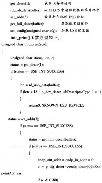
The enumeration initialization process of the printer is very important. To print the collected parallel port data, the printer must first be successfully enumerated and initialized. The initialization USB printer function init_print() mainly uses the following main functions:
 |
|---|
 |
 |
|
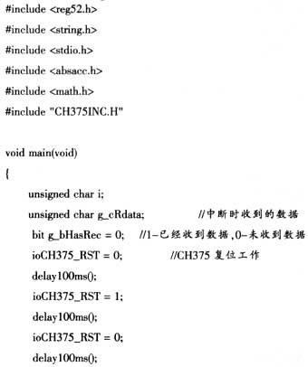
4.2 Main program source code The main program code is as follows: |
 |
 |
 |
|---|
5 Conclusion
This article introduces in detail the design and C language implementation of the LPT-USB printer driver based on the 80C51 microcontroller and the CH375 USB bus universal interface circuit. The test results show that this design can be used to print parallel port instrument data directly through a USB printer, and the printing results are correct. This design is now used on parallel port instruments. Parallel port instruments can use this driver to directly connect to a USB printer and print. This overcomes the disadvantage that some parallel port instruments must be connected to a parallel port printer to print, making it convenient for users.
Previous article:Hydrographic cableway testing system constructed using AT89 microcontroller
Next article:Design of LPT-USB printer driver based on CH375
Recommended ReadingLatest update time:2024-11-16 16:22
- Popular Resources
- Popular amplifiers
 Professor at Beihang University, dedicated to promoting microcontrollers and embedded systems for over 20 years.
- Innolux's intelligent steer-by-wire solution makes cars smarter and safer
- 8051 MCU - Parity Check
- How to efficiently balance the sensitivity of tactile sensing interfaces
- What should I do if the servo motor shakes? What causes the servo motor to shake quickly?
- 【Brushless Motor】Analysis of three-phase BLDC motor and sharing of two popular development boards
- Midea Industrial Technology's subsidiaries Clou Electronics and Hekang New Energy jointly appeared at the Munich Battery Energy Storage Exhibition and Solar Energy Exhibition
- Guoxin Sichen | Application of ferroelectric memory PB85RS2MC in power battery management, with a capacity of 2M
- Analysis of common faults of frequency converter
- In a head-on competition with Qualcomm, what kind of cockpit products has Intel come up with?
- Dalian Rongke's all-vanadium liquid flow battery energy storage equipment industrialization project has entered the sprint stage before production
- Allegro MicroSystems Introduces Advanced Magnetic and Inductive Position Sensing Solutions at Electronica 2024
- Car key in the left hand, liveness detection radar in the right hand, UWB is imperative for cars!
- After a decade of rapid development, domestic CIS has entered the market
- Aegis Dagger Battery + Thor EM-i Super Hybrid, Geely New Energy has thrown out two "king bombs"
- A brief discussion on functional safety - fault, error, and failure
- In the smart car 2.0 cycle, these core industry chains are facing major opportunities!
- The United States and Japan are developing new batteries. CATL faces challenges? How should China's new energy battery industry respond?
- Murata launches high-precision 6-axis inertial sensor for automobiles
- Ford patents pre-charge alarm to help save costs and respond to emergencies
- New real-time microcontroller system from Texas Instruments enables smarter processing in automotive and industrial applications
- [Mill MYB-YT507 development board trial experience] tkinter Button learning
- Learn MSP430G2755 Main Bootloader UART Porting
- Award-winning live broadcast | ADI motor control solutions
- [Xianji HPM6750EVKMINI Review] 1# Hardware Introduction and Development Environment Construction
- How can an electric mosquito swatter kill mosquitoes without harming people? Is it because the voltage is high and the time is short? Isn't that related to ESD?
- Competition sharing, Xiaobai unboxing
- Tips for beginners in electronics
- FPGA design solutions for various EDA tools
- I need help~What is the interface level standard of DAC8812ICPW?
- Today's broadcast starts at 10:00: Interpreting ON Semiconductor's power solutions and understanding the latest power technology trends

 Principle and maintenance of automobile on-board network system (CAN-BUS)


 京公网安备 11010802033920号