0 Introduction
TI's MSP430 series of mixed signal processors are one of the products in the current mainstream MCU market. They are widely used in the field of electronic applications and are favored by more and more electronic designers due to their powerful processing capabilities, high peripheral device integration, low power consumption, comprehensive product series, and full range of industrial grade. Many MSP430 microcontroller circuit designers have encountered problems in design, debugging, and application, such as the system not working or incorrect status after power-on due to reset circuit design problems. Although the probability of this happening is very low, for applications with high reliability requirements, this phenomenon still needs to be paid enough attention by electronic designers.
To this end, this paper conducts a detailed and in-depth analysis of the reset system and reset mechanism of the MSP430 full series of microcontrollers, and specifically proposes a specific peripheral reset circuit design scheme and a detailed introduction to related electronic components for reference and communication among peers.
1 MSP430 reset mechanism
1.1 MSP430 reset circuit
The reset circuit of MSP430 includes a power-on reset (POR) and a power-on clear signal (PUC). POR is a device reset signal, which is usually triggered when the following three events occur: a. Power on; b. RST/NMI pin appears low level in reset mode; c. Voltage monitoring device (Brownout) triggers.
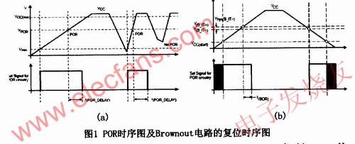
The POR timing is shown in Figure 1(a).

When the supply voltage VCC rises slowly, the POR monitor keeps the POR signal valid until VCC exceeds the VPOR level; when the supply voltage VCC rises quickly, the POR delay t (POR DELAY) provides a valid POR signal long enough to ensure that the MSP430 has enough time to initialize.
1.2 Brownout circuit
The Brownout circuit is a circuit for resetting the voltage when the circuit is under voltage. It replaces the POR detection and POR delay circuits. The Brownout circuit can detect the lower supply voltage value during power-on or power-off, and can reset the chip by triggering the POR signal during power-on or power-off. Figure 1(b) shows the reset timing of the Brownout circuit. As can be seen from the figure, the POR signal is valid when VCC exceeds the start voltage VCC(start-t), and the POR signal remains valid until the VCC voltage value is higher than the limit voltage V(B_IT+) and after a delay of t(BOR); the hysteresis voltage Vhys(B_IT-) is used to ensure that the supply voltage must be lower than V(B_IT-) before the Brownout circuit generates the next POR signal.
1.3 Analysis of reset failure process
In the case of no Brownout reset circuit, if the power supply of MSP430 is periodic, when the power is powered on again, the power supply voltage VCC must be lower than Vmin (see Figure 1) during the decline period of the previous cycle or when disturbed to ensure the occurrence of the POR signal. If VCC cannot be lower than Vmin, the POR signal will not be generated. At this time, even if a low-level signal appears in RST/NMI, a valid POR signal will not be generated and the system cannot be reset normally.
Brownout reset circuit exists in some MSP430 series chips, such as MSP430F13X and MSP430F14X series do not have Brownout circuit. For chip application systems without Brownout circuit, due to interference, power grid fluctuations, misoperation and other reasons, a short voltage drop causes the voltage to fail to meet the POR condition (lower than Vmin) when the power supply is restored. The low-level reset signal at the reset end cannot restart the system to reset the system, and the system freezes. Although this phenomenon does not occur frequently, it is fatal to remote automatic control systems that cannot be manually reset at any time.
Before designing the circuit, carefully read the product technical manual and design different reset circuits according to the different application conditions of each series of chips.
2 Reset circuit design method
2.1 Raising the reset threshold
Increase the reset threshold Vpor' of MSP430, make Vpor' be within the normal working voltage range of MSP430, and close to the minimum threshold Vcc min when MCU is working normally. At this time, it can be guaranteed that when the power supply voltage is near Vcc min and MCU can still work normally, a reset signal is sent to MSP430 at the threshold. At this time, the value of Vpor should be between the lower limit of the power supply (Vp min) and the lower limit of the normal working voltage of MSP430 (Vcc min). As shown in Figure 3.

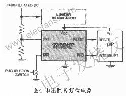
MSP430F149 is one of the most widely used MSP430 chips. Its operating voltage range is between Vcc min=1.8V and Vcc max=3.6V. When the low voltage drop linear regulator TP-S76033 is selected, its supply voltage Vp max=3.34V and Vp min=3.23V. At this time, the reset threshold range should be between 3.23V and 1.8V. In order to improve the conditions for reliable operation of the system, Vpor should be selected as low as possible. Select the reset chip MAX809S (as shown in the right figure of Figure 4), and its reset threshold is 2.89V (Vpor min)
This method is suitable for situations where the tolerance of the power supply system is very small and the power supply voltage accuracy is very high.
2.2 Prolonging the external reset signal time
Since the internal POR of MSP430 only provides reset when powered on, the above method cannot trigger an effective reset when the supply voltage drops below Vpor but is still above Vcc-min and recovers quickly (the second voltage drop shown in Figure 1 (a)). In this case, you can extend the duration of the reset signal or increase the reset cycle. Allowing the reset signal to maintain a sufficiently long period after the voltage value recovers can still cause the chip to reset normally. The MAX809S can maintain an effective reset signal for up to 140ms, which is much longer than the sum of the effective reset signal requirement time (25μs) of the MSP430F149 and the POR signal maintenance time (250μs). When the system encounters voltage fluctuations within a period of 120ms, it can ensure that the system is reset correctly.
By using the reset chip MAX803 with a watchdog timer, the reset signal sending interval can be controlled to be as long as 1s, which is suitable for use in voltage fluctuations with longer periods.
2.3 Monitoring Power Supply
For power supply systems with a large tolerance range (such as when the range of Vp in Figure 3 (a) is greater than or close to the range of VCC), low voltage accuracy, or when the power grid is operating in an undervoltage state for a long time, simply lowering the reset voltage threshold will cause the system to reset frequently under normal working conditions. At this time, the power supply voltage can be monitored. When the above voltage fluctuations are detected, the monitoring chip sends a voltage abnormality signal to the MSP430. The MSP430 responds to the signal and interrupts the running program to enter the power-off protection subroutine and set the reset status register to avoid the failure to start the POR reset due to the register status error at the next power-on.
The MAX6342 is a reset chip with an internal power-fail comparator. The comparator feeds the unstable voltage into the regulator and generates power for the processor and monitoring circuits. Because the unstable voltage drops before the regulator output voltage, a power-fail signal (PFO) is generated after detecting an unstable or lower voltage. The MSP430 enters the power-down processing procedure before being reset.

3 Conclusion
For the sub-series MSP430 microcontrollers with different internal reset mechanisms (Brownout circuits), in the face of different system working environments, the reset circuit can be designed by increasing the reset threshold, extending the reset time, and monitoring the voltage source, which can effectively avoid the problem of occasional reset failures encountered in actual applications and improve the reliability of the system. Practice has shown that the above method can effectively reduce the occurrence of occasional reset failures in the system.
Previous article:Research and implementation of vehicle-mounted blood bank temperature monitoring system
Next article:Design of multifunctional experimental instrument based on ATmega8 single chip microcomputer
Recommended ReadingLatest update time:2024-11-16 23:42


- Popular Resources
- Popular amplifiers
-
 MSP430 series single chip microcomputer system engineering design and practice
 -
 oled multi-chip calling program
 -
 Microcontroller Principles and Applications Tutorial (2nd Edition) (Zhang Yuanliang)
 -
 Getting Started and Improving MSP430 Microcontrollers - National Undergraduate Electronic Design Competition Training Course
 Professor at Beihang University, dedicated to promoting microcontrollers and embedded systems for over 20 years.
- Innolux's intelligent steer-by-wire solution makes cars smarter and safer
- 8051 MCU - Parity Check
- How to efficiently balance the sensitivity of tactile sensing interfaces
- What should I do if the servo motor shakes? What causes the servo motor to shake quickly?
- 【Brushless Motor】Analysis of three-phase BLDC motor and sharing of two popular development boards
- Midea Industrial Technology's subsidiaries Clou Electronics and Hekang New Energy jointly appeared at the Munich Battery Energy Storage Exhibition and Solar Energy Exhibition
- Guoxin Sichen | Application of ferroelectric memory PB85RS2MC in power battery management, with a capacity of 2M
- Analysis of common faults of frequency converter
- In a head-on competition with Qualcomm, what kind of cockpit products has Intel come up with?
- Dalian Rongke's all-vanadium liquid flow battery energy storage equipment industrialization project has entered the sprint stage before production
- Allegro MicroSystems Introduces Advanced Magnetic and Inductive Position Sensing Solutions at Electronica 2024
- Car key in the left hand, liveness detection radar in the right hand, UWB is imperative for cars!
- After a decade of rapid development, domestic CIS has entered the market
- Aegis Dagger Battery + Thor EM-i Super Hybrid, Geely New Energy has thrown out two "king bombs"
- A brief discussion on functional safety - fault, error, and failure
- In the smart car 2.0 cycle, these core industry chains are facing major opportunities!
- The United States and Japan are developing new batteries. CATL faces challenges? How should China's new energy battery industry respond?
- Murata launches high-precision 6-axis inertial sensor for automobiles
- Ford patents pre-charge alarm to help save costs and respond to emergencies
- New real-time microcontroller system from Texas Instruments enables smarter processing in automotive and industrial applications
- This circuit is for audio amplification. Please explain it to me.
- Modification of 4-20mA two-wire passive digital display meter Part 10 (Small task completed)
- Looking for AD component integrated library package library
- TMS320C6678 Evaluation Module
- Power Line Communication Simulation Reference Design for RS-485
- Buck circuit ripple test oscilloscope settings problem
- Implementing Inductive Proximity Sensing with a Single Chip
- 2596 ADJ proportional resistance selection
- Transformer noise
- The circuit board failed the EMC certification, and the signal is unstable! Why can I just add a small return capacitor?

 MSP430 series single chip microcomputer system engineering design and practice
 oled multi-chip calling program


 京公网安备 11010802033920号