O Introduction
Profibus is an open standard that has nothing to do with manufacturers and has no intellectual property protection. Therefore, anyone in the world can obtain the standard and design their own software and hardware solutions. There are two options for the development of the Profibus-DP communication interface: single-chip microcomputer + software; single-chip microcomputer + Profibus communication chip ASIC.
In solution 2, the Profibus-DP protocol is completely implemented by the Profibus communication ASIC, and the microcontroller mainly processes the user program. Therefore, the development cycle of solution 2 is relatively much shorter. This article will use the microcontroller + Profibus communication ASIC to implement the design of the Profibus communication interface.
1 Basic characteristics of Profibus-DP
Profibus includes three compatible series: Profibus-FMS, Profibus-DP, Profibus-PA. FMS provides a large number of communication services for completing cyclic and non-cyclic communication services at medium transmission speed; DP is an optimized high-speed and low-cost communication connection, suitable for occasions with high real-time requirements, mainly used for communication between automatic control and distributed peripherals; PA is designed for process automation, has intrinsic safety, and is used in occasions with high safety requirements and bus-powered stations.
1.1 Protocol Structure
The Profibus-DP protocol uses the first layer (physical layer) and the second layer (data link layer) of the ISO/OSI model, removes layers 3 to 7, and customizes the user interface layer. This protocol structure ensures fast and effective data transmission.
1.2 Message Structure
Profibus-DP data encoding uses asynchronous non-return-to-zero system, and the no-load level of the transmission line is "1". In order to avoid data loss caused by conflicts during data transmission, a 33-bit (synchronous time) no-load state must be guaranteed before each request message is sent. There is no gap when all data is transmitted between single characters, that is, seamless. The formats of various messages are shown in Figure 1.

1.3 Profibus-DP slave state machine
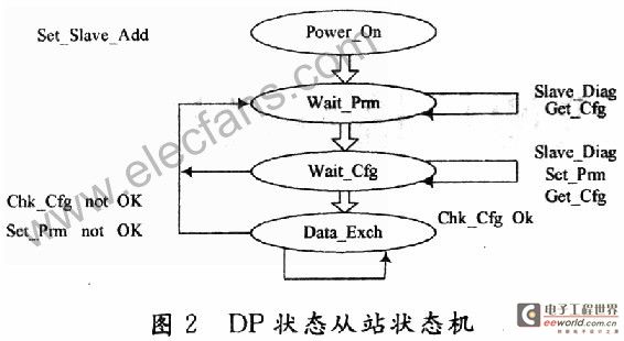
Figure 2 is a simple diagram of the DP slave state machine. The various ovals represent different states, the lines with arrows represent the transitions between states, and the text on the lines represents the conditions that must be met for the state transitions.

Only in the Power_on state can the slave station receive the "Set_Slave_Address" message from the Class II master station to change the slave station address. The slave station should have a non-volatile memory to store the slave station address. After internal startup, the slave station enters the wait_Prm state and waits for the "Wait_Prm" message. The parameterization message is given by the user during configuration, including some standard information, such as identification number, synchronization locking capability, and some user-defined data. In addition, in this state, the slave station can also receive the "Get_Cfg" message and the "Slave_Diag" message, but refuses to process other messages and cannot communicate data. If Set_Prm is correct, the slave station enters the wait_Cfg state and waits for the "Check_Cfg" message, which specifies the master station's configuration information for it, that is, the number of input and output bytes in data exchange. In addition, the "Get_Cfg" message and the "Slave_Diag" message can also be received. When the parameterization and configuration communicate correctly, in this state, the slave can receive the following messages: Data_Exchange_Ok, Writing_outputs, Reading_Inputs, Global_Control, Slave_Diag, Get_Cfg, etc. After receiving the status request from the master, the slave responds with a high-priority diagnostic message. The diagnostic information includes standard diagnostic information and user-related information.
2 Communication Interface Hardware Design
The Profibus-DP communication protocol chip selected in this article is SPC3. SPC3 integrates all Profibus-DP protocols. SPC3 will complete all DP-SAP settings in DP mode. SPC3 integrates 1.5 KB of dual-port RAM, including parameter registers, mode registers, status registers, interrupt controllers, etc. The watchdog timer integrated in SPC3 has three working states: baud rate detection, baud rate control and slave control. The internal USART can realize the mutual conversion between parallel data streams and serial data streams. The micro-sequence controller controls the entire working process. The idle timer directly controls the timing of the serial bus.

Considering the speed requirements of Profibus, this paper selects the high-speed, low-power 16-bit MSP430 microcontroller and adopts the Intel working mode. The CPU and SPC3 interface circuit is shown in Figure 3. For the MSP430 microcontroller, SPC3 is equivalent to an external RAM that it expands. The microcontroller can access the register of SPC3 by accessing the external RAM. One end of the RS 485 driver is connected to SPC3, and the other end is connected to the bus through a 9-pin D-type plug. The RS 485 driver selects SN75SLS176 to meet high-speed data communication.
3 Communication interface software design
Software design is an important part of developing the Profibus-DP communication interface. Since SPC3 integrates the complete DP protocol, the MSP430 microcontroller does not need to participate in processing the DP state machine during communication. The main task is to transfer the data received by SPC3 according to the interrupt generated by SPC3, organize the data to be sent through SPC3, and organize external diagnosis according to requirements.

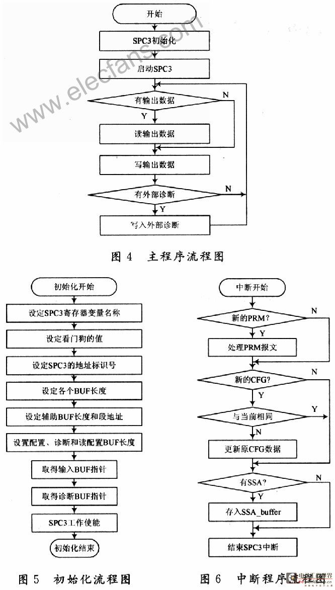
The main program flow chart is shown in Figure 4. Before SPC3 works normally, it needs to be initialized to configure the required registers, including setting the interrupt enable of the protocol chip, writing the slave identification number and address, setting the SPC3 mode register, setting the diagnostic buffer, configuring the buffer, address buffer, initializing the length, and deriving the pointers of each buffer and the auxiliary buffer according to the above initial values. According to the determination of the output buffer, input buffer and pointer, the initialization flow chart is shown in Figure 5. The initialization includes: SPC3 hardware reset, hardware mode, setting the SPC3 interrupt mask register, SPC3 internal watchdog, device identification number, and buffer initialization.
The interrupt program flow chart is shown in Figure 6. In Profibus-DP, the following interrupt events are mainly processed: new parameter message event, global control command message event, entering or exiting data exchange state event, new configuration message event, new address setting message event, baud rate detected event, and watchdog event.
4 Conclusion
The selected MSP430 microcontroller has the characteristics of high speed and low power consumption, and the SPC3 chip integrates all the Profibus-DP protocol content. The whole system function is relatively complete and the method of use is simple. This solution is used for the development of Profibus-DP communication interface, which can reduce the development cycle and simplify the development.
Previous article:CRC algorithm and working principle
Next article:Design of resistive touch screen interface based on ADS7846
Recommended ReadingLatest update time:2024-11-16 16:32


- Popular Resources
- Popular amplifiers
 Professor at Beihang University, dedicated to promoting microcontrollers and embedded systems for over 20 years.
- Innolux's intelligent steer-by-wire solution makes cars smarter and safer
- 8051 MCU - Parity Check
- How to efficiently balance the sensitivity of tactile sensing interfaces
- What should I do if the servo motor shakes? What causes the servo motor to shake quickly?
- 【Brushless Motor】Analysis of three-phase BLDC motor and sharing of two popular development boards
- Midea Industrial Technology's subsidiaries Clou Electronics and Hekang New Energy jointly appeared at the Munich Battery Energy Storage Exhibition and Solar Energy Exhibition
- Guoxin Sichen | Application of ferroelectric memory PB85RS2MC in power battery management, with a capacity of 2M
- Analysis of common faults of frequency converter
- In a head-on competition with Qualcomm, what kind of cockpit products has Intel come up with?
- Dalian Rongke's all-vanadium liquid flow battery energy storage equipment industrialization project has entered the sprint stage before production
- Allegro MicroSystems Introduces Advanced Magnetic and Inductive Position Sensing Solutions at Electronica 2024
- Car key in the left hand, liveness detection radar in the right hand, UWB is imperative for cars!
- After a decade of rapid development, domestic CIS has entered the market
- Aegis Dagger Battery + Thor EM-i Super Hybrid, Geely New Energy has thrown out two "king bombs"
- A brief discussion on functional safety - fault, error, and failure
- In the smart car 2.0 cycle, these core industry chains are facing major opportunities!
- The United States and Japan are developing new batteries. CATL faces challenges? How should China's new energy battery industry respond?
- Murata launches high-precision 6-axis inertial sensor for automobiles
- Ford patents pre-charge alarm to help save costs and respond to emergencies
- New real-time microcontroller system from Texas Instruments enables smarter processing in automotive and industrial applications
- The pinout has changed, where should I modify?
- EMC signal integrity test 1---get out of the metaphysics
- Bluetooth protocol specifications (HCI, L2CAP, SDP, RFOCMM)
- Keep up with the future and enter the NXP Technology Center lecture hall to watch the removable development board, AI-IoT series of books, and red envelopes
- A USB20 communication design for real-time image system.pdf
- STBLESensor Android APP 4.8.0
- Discussion on some details of dual independent clock fifo
- ir2110 drives MOS tube. Help
- Counting the number of people around you using ESP32
- Download: Qorvo Internet of Things For Dummies 2nd Edition

 Mission-oriented wireless communications for cooperative sensing in intelligent unmanned systems


 京公网安备 11010802033920号