In order to ensure that the solar power generation system can work normally, it is necessary to measure the various environmental parameters of the solar power generation system so as to effectively control its operation. This paper introduces a solar parameter tester based on a single-chip microcomputer, which provides three parameter measurement functions and a communication interface, as well as two power supply methods. It can be used as a handheld device and can also be installed in a power generation system, and has high practical value.
1 Hardware Circuit Design
1.1 Overall structure
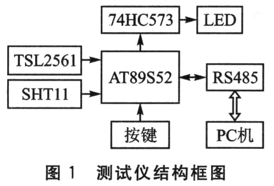
The tester is based on the AT89S52 single-chip microcomputer, with external temperature and humidity sensor SHT11, illumination sensor TSL2561, four-digit common cathode digital tube, RS485 bus communication interface and display switch button. After the single-chip microcomputer is powered on, the current temperature, humidity and light intensity are measured in real time, and the three measured parameters are displayed in turn through the LED digital tube through the key switch; in addition, it can also communicate with the PC through the RS485 bus and transmit the parameter value to the host computer to achieve the purpose of remote monitoring. The structural block diagram of the tester is shown in Figure 1.
1.2 Measurement module
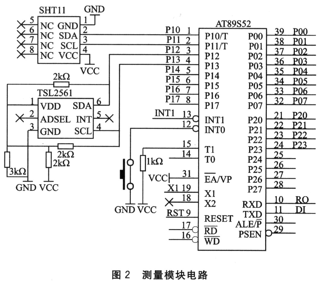
The temperature and humidity measurement uses the SHTll sensor produced by the Swiss company Sensirion. The sensor uses the unique CMOsens TM technology, integrating the temperature and humidity sensor, signal amplification processing, A/D conversion, and I2C bus on a single chip, which can be directly interfaced with the single-chip microcomputer. The chip uses digital output, which provides convenience for programming.
The light intensity sensor TSL2561 produced by TAOS is used for illuminance measurement. It has a digital output port and a standard I2C bus interface, covering a wide illuminance range of 1 to 70,000 lx, which is very suitable for measuring light intensity in outdoor environments and for solar power generation systems. Figure 2 shows the interface circuit design between the sensor and the AT89S52 microcontroller.
1.3 Power Module
The power module provides two power supply modes:
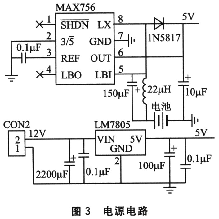
① When the tester is used as a handheld device, a 3.6V lithium battery can be used directly. After the DC-DC voltage conversion chip MAX756 increases the voltage to 5V, it can power the microcontroller and peripherals.
② When the tester is installed as a fixed device at a solar power generation site, it can be powered by solar energy. The 12 V voltage generated by the solar cell passes through the voltage regulator chip LM7805 to obtain a stable 5 V voltage output. The output voltage can not only power the test module but also charge the lithium battery through the charging circuit. Figure 3 is the hardware schematic diagram of the power module.
1.4 Charging Circuit
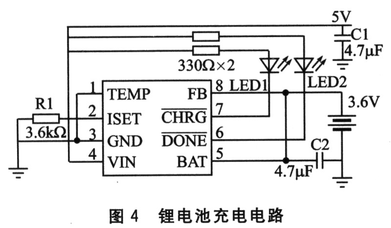
The core device of the charging circuit is the dedicated charging chip CN3058 produced by Shanghai Ruyun Company, which can charge a single-cell lithium iron phosphate rechargeable battery with constant current/constant voltage. The device has an integrated power transistor, and does not require the design of peripheral current detection and protection circuits when used, making it suitable for portable applications.
Figure 4 is a lithium battery charging circuit, where LED1 and LED2 are used as indicator lights for charging and saturation respectively, R1 plays a role of current limiting protection during charging; capacitors C1 and C2 are multilayer ceramic capacitors (MLCC), which can ensure stable operation of the charging circuit.
1.5 Communication Module
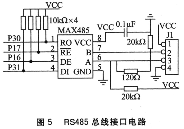
The tester communicates with the PC via the RS485 industrial bus, and its hardware interface circuit is shown in Figure 5.
2 Software Design
2.1 Overall design
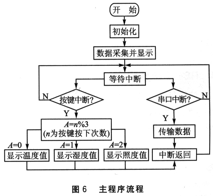
The software development environment of the tester is Keil C, and all codes are written in C language. In order to facilitate program debugging and improve reliability, the software adopts a modular structure design, which is mainly composed of initialization program, main program, subroutine, interrupt service program, etc. After the microcontroller is powered on, it starts to execute the temperature, humidity and illumination measurement program in a loop, and dynamically displays them on the digital tube in turn at set time intervals; the key switching and communication function parts are relatively low in frequency of use, so in order to reduce the power consumption of the equipment, their programs are executed in the form of interrupt response. Here, it is necessary to pay attention to the setting of interrupt priority: the key interrupt priority should be higher than the serial port interrupt, otherwise the display switching will not be possible. The main program flow is shown in Figure 6.
2.2 Sensor Driver
The sensors used in this system are all integrated digital chips and have I2C bus interfaces, so the writing of their drivers must strictly follow the timing of the I2C bus. The main program opens up an 8-bit storage space for each parameter. The sensor outputs the collected data serially through the SDA pin. The driver converts the data output on the SDA line into serial-to-parallel and stores it in the corresponding space to facilitate other functional program calls. The following is part of the code for the illumination sensor data acquisition program.
(1)TSL2561 initialization

2.3 RS485 communication program
The communication between the tester and the host computer adopts RS485 protocol. The serial port parameters are: baud rate 9600, data bit 8, 1 check bit, 1 stop bit. Its data format is shown in Figure 7.

Since the RS485 bus protocol and the RS232 serial port protocol only differ in the interface level, their software programming is completely carried out in accordance with the serial port communication protocol and will not be described in detail here.
Conclusion
Through experimental tests, the temperature measurement and display accuracy of the environmental parameter tester can reach 0.1℃, the humidity is accurate to 0.1%, and the illumination can be accurate to 11x. Since the main components are all I2C digital interfaces, this tester also has the characteristics of simple structure, easy maintenance, strong scalability, etc., and has high practical value; in addition, the unique dual power supply mode further expands its scope of application.
Previous article:Design of multi-point temperature control system based on 51 single chip microcomputer
Next article:Temperature telemetry and remote control system based on C8051F040 single chip microcomputer
Recommended ReadingLatest update time:2024-11-17 00:55


- Popular Resources
- Popular amplifiers
-
 Siemens S7-1200-PLC Programming and Application Tutorial (3rd Edition) (Edited by Shi Shouyong)
 -
 西门子S7-12001500 PLC SCL语言编程从入门到精通 (北岛李工)
 -
 100 Examples of Microcontroller C Language Applications (with CD-ROM, 3rd Edition) (Wang Huiliang, Wang Dongfeng, Dong Guanqiang)
 -
 Principles and Applications of Single Chip Microcomputers 3rd Edition (Zhang Yigang)
 Professor at Beihang University, dedicated to promoting microcontrollers and embedded systems for over 20 years.
- Innolux's intelligent steer-by-wire solution makes cars smarter and safer
- 8051 MCU - Parity Check
- How to efficiently balance the sensitivity of tactile sensing interfaces
- What should I do if the servo motor shakes? What causes the servo motor to shake quickly?
- 【Brushless Motor】Analysis of three-phase BLDC motor and sharing of two popular development boards
- Midea Industrial Technology's subsidiaries Clou Electronics and Hekang New Energy jointly appeared at the Munich Battery Energy Storage Exhibition and Solar Energy Exhibition
- Guoxin Sichen | Application of ferroelectric memory PB85RS2MC in power battery management, with a capacity of 2M
- Analysis of common faults of frequency converter
- In a head-on competition with Qualcomm, what kind of cockpit products has Intel come up with?
- Dalian Rongke's all-vanadium liquid flow battery energy storage equipment industrialization project has entered the sprint stage before production
- Allegro MicroSystems Introduces Advanced Magnetic and Inductive Position Sensing Solutions at Electronica 2024
- Car key in the left hand, liveness detection radar in the right hand, UWB is imperative for cars!
- After a decade of rapid development, domestic CIS has entered the market
- Aegis Dagger Battery + Thor EM-i Super Hybrid, Geely New Energy has thrown out two "king bombs"
- A brief discussion on functional safety - fault, error, and failure
- In the smart car 2.0 cycle, these core industry chains are facing major opportunities!
- The United States and Japan are developing new batteries. CATL faces challenges? How should China's new energy battery industry respond?
- Murata launches high-precision 6-axis inertial sensor for automobiles
- Ford patents pre-charge alarm to help save costs and respond to emergencies
- New real-time microcontroller system from Texas Instruments enables smarter processing in automotive and industrial applications
- How to configure the timer?
- Digitally controlled DCDC converter
- How to deal with the prompt "Transient time point calculation did not converge" during Multisim simulation
- What are the configurations of the computer that ranks fourth in the world?
- Hahaha
- The development board is connected to the Internet via a shared network
- Thonny Python Editor upgraded to 4.0.0 Beta1
- control
- DSP water light source program
- Embracing the era of big data and interpreting 5G communication clock synchronization technology

 Siemens S7-1200-PLC Programming and Application Tutorial (3rd Edition) (Edited by Shi Shouyong)
 西门子S7-12001500 PLC SCL语言编程从入门到精通 (北岛李工)


 京公网安备 11010802033920号