O Introduction
At present, the market and embedded system products for scientific research in colleges and universities, such as Vxworks, Linux and Windows CE, are quite mature and provide powerful development and debugging tools. However, some development costs are expensive and the cycle is long, while μC/OS- Ⅱ is a multi-task real-time source code open operating system with a streamlined kernel and strong portability, which is very suitable for the development of some small control and experimental systems.
1 Introduction to operating system and CPU
μC/OS-II is a priority-based preemptive real-time multi-tasking operating system, which includes tasks management, time management, inter-task synchronous communication (semaphores, mailboxes, message queues) and memory management functions. Most of the code is written in C language, and a very small number of codes closely related to the processor are written in assembly language to facilitate portability. As a real-time operating system with open source code, it can manage up to 64 tasks and supports a variety of inter-process communication mechanisms such as semaphores, mailboxes, and message queues. At the same time, users can tailor the functional modules in the kernel according to their needs.
LPC2378 is an embedded reduced instruction set microcontroller based on the ARM7TDMI-S core. It contains an ARM7TDMI-SCPU that supports simulation and is suitable for applications that require serial communication for various purposes. The architecture supports 7 processor modes including user, soft interrupt, interrupt, management, abort, undefined, and system. There are 31 general-purpose 32-bit registers and 6 status registers inside the ARM7TDMI-S processor. LPC2378 contains a 10/100 EthernetMAC, USB 2.0 full-speed interface, 4 UART interfaces, 2 CAN channels, 1 SPI interface, 2 synchronous serial ports (SSP), 3 I2C interfaces, 1 I2S interface and MiniBus (MiniBus is only used for LPC2378, it is an 8-bit data/16-bit address parallel bus). The following takes the transplantation of μC/OS-Ⅱ on the industrial-grade chip LPC2378 as an example, and introduces the general methods and processes of μC/OS-Ⅱ operating system transplantation and the solutions to related problems by analyzing the operating system kernel.
2 μC/OS-Ⅱ kernel structure and working principle
2.1 Basic structure of the kernel
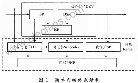
Figure 1 is a simple kernel architecture diagram close to μC/OS-Ⅱ. The kernel has three interfaces reserved for upper-layer applications, namely soft protection, ITC and DSR. Since the μC/OS-Ⅱ operating system kernel is a deprivable real-time multitasking kernel, the highest priority task can always get the right to use the CPU once it is ready. If the interrupt service subroutine puts a high-priority task into the ready state, when the interrupt is completed, the interrupted task is suspended and the high-priority task starts running.
2.2 Basic working principle of μC/OS-Ⅱ kernel
In a multi-tasking system, the operating system kernel is responsible for managing each task, or allocating a CPU to each task, and is responsible for communication and collaboration between tasks. Task switching is a basic service provided by the kernel. The basic working principle of μC/OS-Ⅱ multi-tasking operating system is as follows:
(1) Before using all services of μC/OS-Ⅱ, the initialization function OSInit() must be called to initialize all variables and data structures. At the same time, the idle task OSTaskIdle() must be created and given the lowest priority level and permanent ready state. , while completing the initialization of the task control block (TCB), the initialization of the TCB priority table, the initialization of the TCB linked list, and the initialization of the event control block (ECB) linked list.
(2) Call OSTaskCreate() or OSTaskCreateExt() to create at least one new task and assign a certain priority to the task, and they have their own set of CPU registers and their own stack space.
(3) Call the OSSTART() function to find the task control block with the highest priority established by the user from the task ready table, and then start multi-task scheduling.
3 μC/OS-Ⅱ transplantation process on LPC2378 and analysis of related issues
Taking the transplantation on the LPC2378 microcontroller as an example, we analyze the general method of transplanting the μC/OS-II operating system. The development environment used is the integrated development environment ADS1.2 of ARM Company.
3.1 Porting code
(1) The codes of μC/OS-Ⅱ that are independent of the CPU type include μC/OS-Ⅱ.H, μC/OS-Ⅱ.C, OS_CORE.C, OS_TASK.C, OS_TIME.C, OS_SEM.C, OS_MBOX.- C, OS_MUTEX.C, OS_FLAG.C, which means these files can be added directly without modification.
(2) The codes related to the CPU type of μC/OS-II include OSCPU.H, OS_CPU_A.ASM, OS_CPU_C.C, which means that the user needs to modify these functions according to the selected CPU type before adding them to the kernel.
3.2 Definition and modification of OS_CPU.H file
The OS_CPU.H file defines compiler- and CPU-related data types, stack width and growth methods, and macro definitions for switching interrupts. Since the stack growth methods supported by microprocessors and microcontrollers are different, the macro OS_STK_GRWOTH needs to be defined based on the type supported by the selected chip LPC2378. Since the ARM7 TD-MI-S kernel stack supports the top-down growth method, Therefore the following definition should be made:
#define OS_STK_GROWTH 1 //The stack is the other three macros OS_CRITICAL_METHOD, OS_ENTER_CRITICAL(), and OS_EXIT_CRITICAL() in the OS_CPU.H file that are long from top to bottom. They are used to define the switch interrupt method and the implementation of the switch interrupt. Protect critical code by calling switch interrupt 2 macros as follows:

3.3 Definition and writing of main functions in the OS_CPU_C.C file
OS_CPU_C.C requires users to write 10 simple functions:

Combined with the hardware and register characteristics of the CPU core to be transplanted, briefly analyze and create the task stack initialization function:
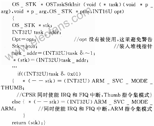
The other nine functions must be declared, but do not necessarily contain task code.
3.4 Transplantation of μC/OS-Ⅱ
The transplantation of μC/OS-Ⅱ also requires the preparation of four simple assembly language functions; namely OSStartHighRdy(), OSintCtxSw(), OSTIckISR(), OSCtxSw().
3.4.1 Function OSStart() calls OSStartHighRdy()
The function OSStart() is used to call OSStartHighRdy() to start the task with the highest priority among the ready tasks:
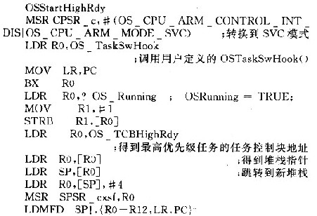
3.4.2 Clock interrupt service routine
μC/OS-Ⅱ requires the user to provide a periodic clock source to implement time delay and timeout confirmation functions. The clock beat occurs 10 to 100 times per second. The clock tick interrupt must be started after starting multitasking. However, since the Osatart() function will not return, the user cannot implement this operation. Therefore, the tick can be initialized in the first task started by μC/OS after OSStart() is run. Interrupt. The simple code of OSTicklSR() based on LPC2378 transplantation is written as follows:
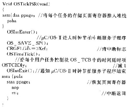
When a clock beat interrupt occurs, the CPU will automatically push the CPU register into the stack, but does not include the storage page register PPAGE. If the addressing range of the microcontroller system exceeds 64 KB, you need to assign a value to PPAGE to distinguish different 16 KB addresses. , you need to push PPAGE into the stack. When the time delay item OSTCBDly in the task control block of a task decreases to zero, OSTi-mtick() enters the ready state. OSIntExit() will call the interrupt-level task switching function OSIntCtxSw to perform task switching instead of executing subsequent instructions. If no higher priority task enters the ready state, the CPU will return to the pre-interrupt state.
3.4.3 Task-level task switching
In fact, task-level switching is achieved by executing soft interrupt instructions or, depending on the processor, executing TRAP instructions. The vector address of the interrupt service subroutine, TRAP or exception handling must point to OSCtXSW(), and the system will automatically push the breakpoint pointer into the stack when jumping to the interrupt service routine, and store the breakpoint pointer on the stack. The interrupt return instruction IRET can push the breakpoint pointer into the PC register function of the CPU and restore the breakpoint of the task to be run, so that the breakpoint can be saved and restored.
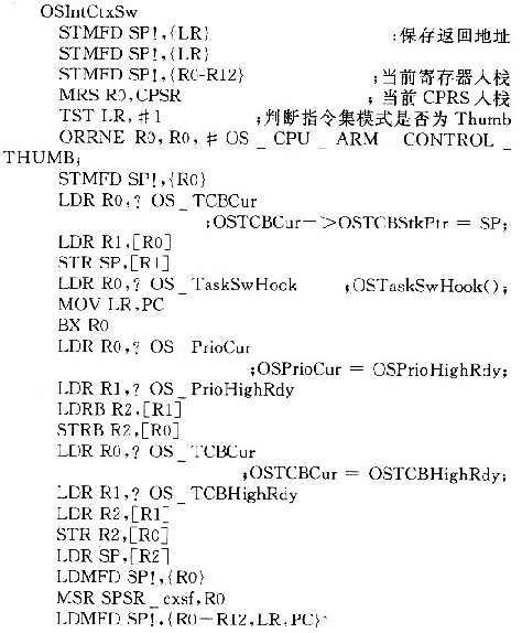
3.4.4 Interrupt level task switching
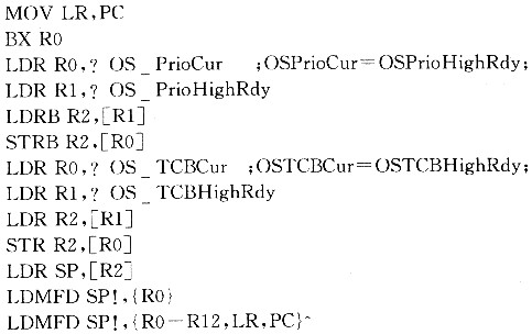
OSIntExit() executes the task switching function in the ISR by calling OSIntSw(). Because OSIntCtxSw() is called in the ISR, it is assumed that all processor registers are correctly saved to the stack of the interrupted task. Most of the code of the OSIntSw() function is the same as the OSCtxSw() function. The only difference is that because the ISR has saved the CPU register, there is no need to save the CPU register in the OSIntSw() function. When transplanting the operating system, the code of this program is as follows:
3.5 Problems in transplantation
The software debugging of the ARM processor runs directly on the system's external SRAM through the JTAG port. Therefore, before program debugging, the ARM processor's development environment software first calls the initialization file (*.ini). The user can adjust the external memory and device according to the system's external memory. address to modify the file. If this file is incorrect, the development environment software will not be able to communicate with the processor via JTAG. During system debugging, programs often run away. After testing and analysis, there are four main reasons:
(1) The interrupt vector address of the interrupt handler is not assigned correctly, resulting in the CPU being unable to run to the interrupt handler location after an interrupt occurs;
(2) Add several NOP empty statements after the task switching statements in OsctxSw and OSIntctxSw to ensure that the corresponding instructions for task switching are completed. If no corresponding no-operation instructions are added at these locations, the program will also run away;
Previous article:Design of motion control system based on CAN bus
Next article:Design of intelligent digital acquisition board based on LPC2138 chip and LP02138 SOC
Recommended ReadingLatest update time:2024-11-22 21:49

![Tiny4412 C language implementation of water lamp, Tiny4412 bare metal program [3]](https://6.eewimg.cn/news/statics/images/loading.gif)


- Naxin Micro and Xinxian jointly launched the NS800RT series of real-time control MCUs
- How to learn embedded systems based on ARM platform
- Summary of jffs2_scan_eraseblock issues
- Application of SPCOMM Control in Serial Communication of Delphi7.0
- Using TComm component to realize serial communication in Delphi environment
- Bar chart code for embedded development practices
- Embedded Development Learning (10)
- Embedded Development Learning (8)
- Embedded Development Learning (6)
 Professor at Beihang University, dedicated to promoting microcontrollers and embedded systems for over 20 years.
- Intel promotes AI with multi-dimensional efforts in technology, application, and ecology
- ChinaJoy Qualcomm Snapdragon Theme Pavilion takes you to experience the new changes in digital entertainment in the 5G era
- Infineon's latest generation IGBT technology platform enables precise control of speed and position
- Two test methods for LED lighting life
- Don't Let Lightning Induced Surges Scare You
- Application of brushless motor controller ML4425/4426
- Easy identification of LED power supply quality
- World's first integrated photovoltaic solar system completed in Israel
- Sliding window mean filter for avr microcontroller AD conversion
- What does call mean in the detailed explanation of ABB robot programming instructions?
- STMicroelectronics discloses its 2027-2028 financial model and path to achieve its 2030 goals
- 2024 China Automotive Charging and Battery Swapping Ecosystem Conference held in Taiyuan
- State-owned enterprises team up to invest in solid-state battery giant
- The evolution of electronic and electrical architecture is accelerating
- The first! National Automotive Chip Quality Inspection Center established
- BYD releases self-developed automotive chip using 4nm process, with a running score of up to 1.15 million
- GEODNET launches GEO-PULSE, a car GPS navigation device
- Should Chinese car companies develop their own high-computing chips?
- Infineon and Siemens combine embedded automotive software platform with microcontrollers to provide the necessary functions for next-generation SDVs
- Continental launches invisible biometric sensor display to monitor passengers' vital signs
- How to suppress surge current in LED lamps?
- Hiring embedded development engineers
- Problems with jtag downloader
- House price concerns
- [Homemade] OLED full-screen watch, smooth playback of Badapple
- What changes will the high-reliability fully integrated automotive eCall switch bring to the automotive industry?
- Holtek Launches 8-bit Dual Slope A/D Microcontroller
- 2018-Toshiba Photorelay TLP3547 Review 1-- Unboxing (Preliminary Test and Learning)
- Streaming, the first-line test results of the domestically produced 800MHz RISC-V MCU HPM6750
- TE IoT exclusive platform is now online, the professional all-round assistant you deserve


 Siemens PLC Project Tutorial


 京公网安备 11010802033920号