Introduction to buzzer
1. The function of the buzzer The buzzer is an electronic buzzer with an integrated structure. It is powered by DC voltage and is widely used in computers, printers, copiers, alarms, electronic toys, automotive electronic equipment, telephones, timers and other electronics. The product is used as a sound-generating device.
2. Classification of buzzers Buzzers are mainly divided into two types: piezoelectric buzzers and electromagnetic buzzers.
3. Buzzer circuit graphical symbols The buzzer is represented by the letter "H" or "HA" in the circuit (the old standard is represented by "FM", "LB", "JD", etc.).
Buzzer classification:
Buzzers are divided into piezoelectric buzzers and electromagnetic buzzers according to different structures; whether they are piezoelectric buzzers or electromagnetic buzzers, there are active and passive distinctions. Among them, "active" "Source" means that the buzzer itself has a built-in driver, and it can sound directly by giving it a certain voltage; "passive" means that it needs an external driver to sound.
The structural principle of the buzzer:
Piezoelectric buzzer: uses the piezoelectric effect of piezoelectric ceramics to drive the vibration of metal sheets to produce sound. It is mainly composed of a multivibrator, a piezoelectric buzzer, an impedance matching device, a resonance box, and a shell. Some piezoelectric buzzers are also equipped with light-emitting diodes on their casings. Multivibrators are constructed from transistors or integrated circuits. When the power is turned on (1.5~15V DC working voltage), the multivibrator starts to oscillate and outputs an audio signal of 1.5~2.5kHZ. The impedance matching device drives the piezoelectric buzzer to sound.
The piezoelectric buzzer is made of lead zirconate titanate or lead magnesium niobate piezoelectric ceramic material. Silver electrodes are plated on both sides of the ceramic sheet, and after polarization and aging treatment, they are bonded together with brass or stainless steel sheets.
Piezoelectric buzzers require relatively high voltage to have sufficient sound pressure, and it is generally recommended to be above 9V. Some specifications of piezoelectric can reach more than 120dB, and larger sizes can easily reach 100dB.
Electromagnetic buzzer: Using the principle of electromagnetism, the metal vibrating diaphragm is sucked down when energized, and rebounds according to the elasticity of the vibrating diaphragm when not energized. It is composed of an oscillator, electromagnetic coil, magnet, vibrating diaphragm and shell. After the power is turned on, the audio signal current generated by the oscillator passes through the electromagnetic coil, causing the electromagnetic coil to generate a magnetic field. The vibrating diaphragm periodically vibrates and produces sound under the interaction of the electromagnetic coil and the magnet.

Buzzer circuit diagram
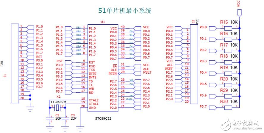
AT89C52 introduction:
AT89C52 is a low-voltage, high-performance CMOS 8-bit microcontroller produced by Atmel Company of the United States. It contains 8KB of rewritable program memory and 12B of random access data memory (RAM). The device adopts Atmel's high-density, non-volatile Produced with volatile storage technology, it is compatible with the standard MCS-51 instruction system. It is equipped with a general-purpose 8-bit central processing unit (CPU) and Flash storage unit on-chip. The powerful AT89C52 microcontroller can be flexibly used in various control fields. The AT89C52 microcontroller is an enhanced version of the AT89C51 microcontroller and is compatible with Intel's 80C52 in terms of pin arrangement, hardware composition, operating characteristics and command system. Its main working characteristics are:
The on-chip program memory contains 8KB of Flash program memory, with a rewritable lifespan of 1,000 times;
The interrupt system is an interrupt structure with 8 interrupt sources, 6 interrupt vectors, and 2 levels of priority;
The serial port is a full-duplex programmable serial communication port; it has a data pointer DPTR;
Low-power working modes include idle mode and power-down mode; with programmable 3-level program lock bit;
The working power supply voltage of AT89C52 is 5 (1+0.2) V, and the typical value is 5V; the maximum working frequency of AT89C52 is 24MHz, here we use 11.0592MHz. The AT89C52 picture is as follows:

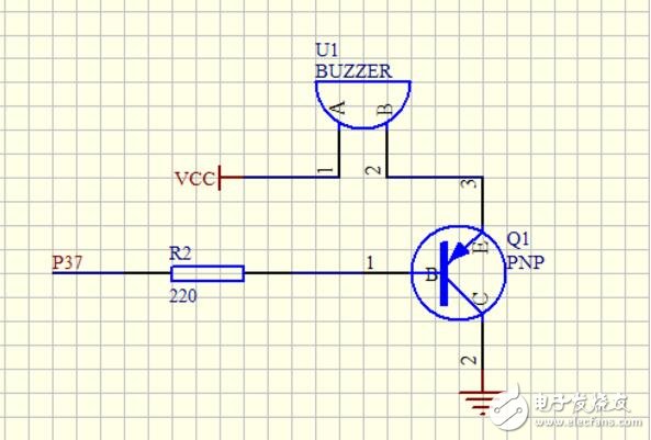
AT89C52 control buzzer circuit diagram
The buzzer circuit consists of a 220 ohm resistor, a transistor 8550, and a buzzer, as shown in Figure 10. By controlling the conduction and cut-off of the transistor, the buzzer can sound or not.


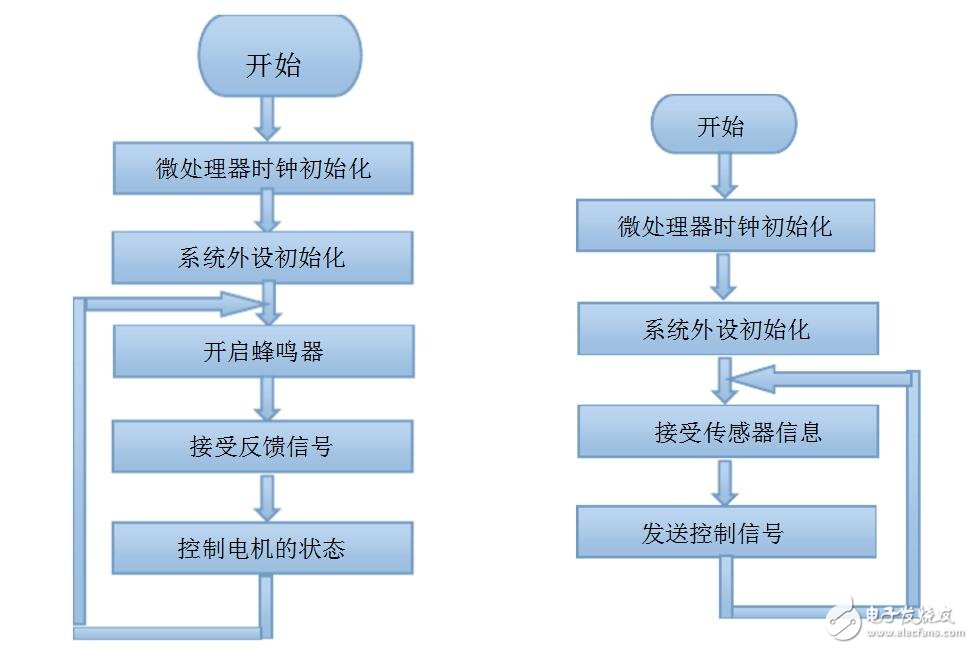
flow chart
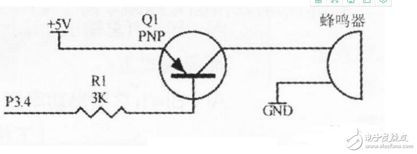
Microcontroller controls the sounding and closing of active buzzer
As you can see from the picture below, the circuit uses the I/0 port P3.4 of the microcontroller to control the buzzer. However, in the figure, P3.4 is not used to directly control the buzzer, but indirectly controlled through the transistor 8550. This is because the current that can flow in and out of the I/0 port of the microcontroller is limited. Some buzzers require a relatively large current to sound, which the I/0 of the microcontroller cannot meet. The transistor 8550 can provide a maximum current of more than 1A, which is enough to drive the buzzer, so P3.4 is used to control the conduction and cutoff of the transistor 8550 to achieve the purpose of controlling the buzzer. Let’s first look at the control principle of this circuit:
When writing logic "1" to P3.4, P3.4 outputs +5V, the base current of the transistor 8550 is 0, the transistor is in a cut-off state, the power supply +5V cannot be added to the positive pole of the buzzer, and the buzzer does not sound. When writing logic "0" to P3.4, P3.4 outputs OV, and a current is generated between the emitter and base of the transistor 8550. In Figure 1, the current limiting resistor R1 takes an appropriate value to make the transistor saturated. In the conduction state, the power supply +5V is added to the positive electrode of the buzzer through the emitter and collector of the triode, and current flows through the positive and negative electrodes of the buzzer, and the active buzzer starts to sound.

In this way, controlling the sound of the active buzzer becomes writing logic "1" or logic "0" to port P3.4. The following program can make the active buzzer sound "beep" and "beep":
#include《reg52.h》
sbitBuzzer=P3h4;1/[Note 1]
//Main program voiDMAin(void){//Loop statement, make the buzzer sound continuously at intervals of 0.5 seconds, stop for(;;){delay(): //Delay 0.5 seconds, for specific procedures, see the previous issue of BUzzerh =1; //[Note 2]
}
}
Previous article:Internal clock circuit design of AT89S51 microcontroller
Next article:89c51 microcontroller minimum system, detailed function explanation of 89c51 minimum system schematic diagram
Recommended ReadingLatest update time:2024-11-16 10:29


- Popular Resources
- Popular amplifiers
-
 西门子S7-12001500 PLC SCL语言编程从入门到精通 (北岛李工)
 -
 Principles and Applications of Single Chip Microcomputers and C51 Programming (3rd Edition) (Xie Weicheng, Yang Jiaguo)
 -
 Teach you to learn 51 single chip microcomputer-C language version (Second Edition) (Song Xuefeng)
 -
 Hand-drawn illustrations revealing the secrets of communication circuits and sensor circuits (Mims III)
 Professor at Beihang University, dedicated to promoting microcontrollers and embedded systems for over 20 years.
- Innolux's intelligent steer-by-wire solution makes cars smarter and safer
- 8051 MCU - Parity Check
- How to efficiently balance the sensitivity of tactile sensing interfaces
- What should I do if the servo motor shakes? What causes the servo motor to shake quickly?
- 【Brushless Motor】Analysis of three-phase BLDC motor and sharing of two popular development boards
- Midea Industrial Technology's subsidiaries Clou Electronics and Hekang New Energy jointly appeared at the Munich Battery Energy Storage Exhibition and Solar Energy Exhibition
- Guoxin Sichen | Application of ferroelectric memory PB85RS2MC in power battery management, with a capacity of 2M
- Analysis of common faults of frequency converter
- In a head-on competition with Qualcomm, what kind of cockpit products has Intel come up with?
- Dalian Rongke's all-vanadium liquid flow battery energy storage equipment industrialization project has entered the sprint stage before production
- Allegro MicroSystems Introduces Advanced Magnetic and Inductive Position Sensing Solutions at Electronica 2024
- Car key in the left hand, liveness detection radar in the right hand, UWB is imperative for cars!
- After a decade of rapid development, domestic CIS has entered the market
- Aegis Dagger Battery + Thor EM-i Super Hybrid, Geely New Energy has thrown out two "king bombs"
- A brief discussion on functional safety - fault, error, and failure
- In the smart car 2.0 cycle, these core industry chains are facing major opportunities!
- The United States and Japan are developing new batteries. CATL faces challenges? How should China's new energy battery industry respond?
- Murata launches high-precision 6-axis inertial sensor for automobiles
- Ford patents pre-charge alarm to help save costs and respond to emergencies
- New real-time microcontroller system from Texas Instruments enables smarter processing in automotive and industrial applications
- Recruitment: Executive Vice President of Automotive Electronics (Executive Vice President of New Energy)
- ATmega4809 Curiosity Nano Review + Unboxing and Powering on
- Sell an unused Jiuxintaike oscilloscope and get a Guwei desktop multimeter for free
- MSP430F1232 external 4M crystal oscillator cannot start
- Q: How do you determine the inductance value when selecting a common-mode coil?
- What does BMS device learning and chemical ID mean?
- [NUCLEO-L452RE Review] + Simple Digital Voltmeter
- Gaoyun FPGA various manuals
- [2022 Digi-Key Innovation Design Competition] ESP32S2 Lighting
- PCB connector connection method

 西门子S7-12001500 PLC SCL语言编程从入门到精通 (北岛李工)


 京公网安备 11010802033920号