1. ARMv7-A processor mode

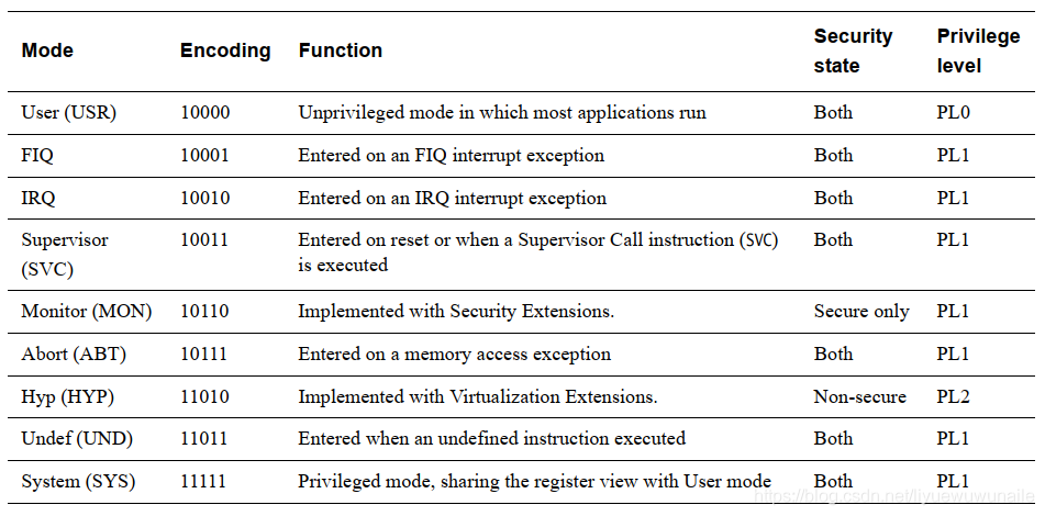
The ARMv7 architecture supports security extensions. If security extensions are enabled, the ARMv7-A architecture is divided into two worlds: secure mode (Secure State) and non-secure mode (Non-secure State).
In non-secure mode, there are three operating privileges PL0, PL1 and PL2 (privilege level).
If the Virtualization Extensions are implemented there is a privilege model different to that of previous architectures. In Non-secure state there can be three privilege levels, PL0, PL1 and PL2.


ARMv7-A General Registers
The ARMv7-A architecture provides 16 32-bit general registers (R0-R15) and a program status register CPSR (Current Program Status Register). In exception mode, the SPSR (Saved Program Status Register) can be accessed. In exception mode, the SPSR is used to save the current CPSR register value. Among them, R0-R14 can be used for ordinary data storage, and R15 is the program counter PC (program counter).

The above registers may correspond to different physical storage locations depending on the operating mode, as shown in the blue area in the figure above. They use different physical storage and are usually only accessible when the process is executed in a specific mode.
R0-R7 correspond to the same physical storage in any mode and are called ungrouped registers;
R8-R14 correspond to different physical storage according to different modes, which are called group registers;
R13 (SP) corresponds to the same physical storage in User and Sys modes, and FIQ, IRQ, ABT, SVC, UND, MON, and HYP modes correspond to different physical storage. R13 is used for SP stack pointer in the ARM architecture. MON mode is used to manage secure and non-secure modes, and HYP mode is used to manage virtual operating systems (GuestOS).
R14 (LR) corresponds to the same physical storage in User, Sys and HYP modes, and corresponds to different physical storage in FIQ, IRQ, ABT, SVC, UND, MON modes. R14 is used as the LR link register in the ARM architecture. In each mode, R14 is used to save the subroutine return address. When executing the BL instruction, R14 is used to back up the value of the R15 register.
R15 (PC) holds the address of the current program execution. In all modes, R15 (PC) shares the same physical storage. In ARM state, [1:0] is 0, and [31:2] is used to hold the PC. In Thumb state, [0] is 0, and [31:1] is used to hold the PC.
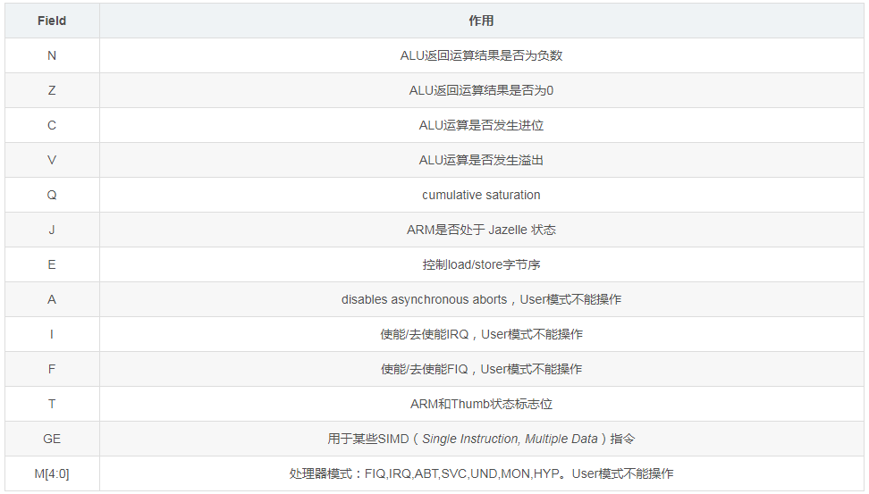
CPSR is the program status register, which saves control and status bits such as conditional flags, interrupt disable bits, and the current processor mode. There is also an SPSR in each exception mode, which saves the CPSR register value before entering the exception mode and is used to restore the CPSR state after the exception processing is completed. User and Sys do not belong to the exception mode and do not have a CPSR register. In User mode, the restricted CPSR register is called APSR (Application Program Status Register). The information of the CPSR register in ARMv7-A is shown in the figure below.

The meaning of each Field is as follows:

3. ARMv7-A Coprocessor CP15 Registers
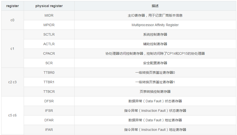
The ARMv7-A architecture protects the system control coprocessor CP15, which is mainly used to handle storage system related functions. CP15 can only be accessed in privileged mode. CP15 provides 16 32-bit main registers, named c0-c15. The c0-c15 registers may correspond to multiple different physical registers.


Coprocessor CP15 register access includes read and write operations.
The read operation is to read the value of register CRn in CP15 into the general register Rt, using the instruction syntax MRC, Op1, Rt, CRn, CRm, Op2;
The write operation is to write the value of the general register Rt into the register CRn in CP15, using the instruction syntax MCR, Op1, Rt, CRn, CRm, Op2;

MRC: read the CP15 register value to the ARM general register;
MCR: Write the ARM general register value to the CP15 register;
Op1: co-processing behavior opcode;
Rt: ARM general register, cannot be R15 (PC);
CRn: coprocessor CP15 register c0-c15;
CRm: Additional target register, if no additional information is required, set to c0;
Op2: To distinguish different physical registers with the same number, for example, to access MIDR and MPIDR in c0, the Op2 values are 0 and 1 respectively. It is set to 0 by default;
Example:
Read the MIDR register in CP15 register c0 into R1.
MRC p15, 0, R1, c0, c0, 0
4. System Control Register CP15.SCTLR
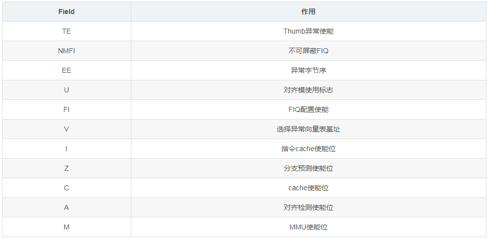
The system control register SCTLR (System Control Register) is used to control memory, system functions and provide status information.


Example:
Initialize CP15:SCTLR, enable cache, instruction cache and branch prediction functions.

Previous article:Linux ARMv7 architecture general interrupt process (1)
Next article:ARM_Core processor mode and registers, structure talk
Recommended posts
- MSP430 IO and internal structure diagram
- MSPhas7addressingmodes,andtheaddressingmodesaresimilartothoseofARM,sothemodesaresimilar.Theselow-levelthingscanonlybeusedbywritinginassemblystatements. MSP430pindistribution:6groupsofI/Oports,8ineachgr
-
fish001
 Microcontroller MCU
- How Designers Achieve Tri-Band Gigabit Speeds and High Throughput in Wi-Fi
- Engineersareconstantlylookingforthesimplestsolutiontocomplexsystemdesignchallenges.ConsidertheU-NII1-8,5,and6GHzsolutions.Inthisarticle,wewillreviewhowbest-in-classbandBoostfilterscanincreasesystemdesigncapacitya
-
兰博
 RF/Wirelessly
- [nRF7002-DK Wi-Fi 6 Development Kit Review] #2 nRF Connect Development Environment Configuration and Installation
- nRFConnectdevelopmentenvironmentconfigurationandinstallation 1Overview nRF'sdevelopmentenvironmentisgenerallyalittlecomplicated.Itisnotaone-stopinstallationandconfiguration.Youneedtogothroughmultipleprogramsth
-
北方
 RF/Wirelessly
- Ti DSP optimization basic strategy
- 1.Theoptimizationprocessisgenerallydividedintothreestages. Phase1:ImplementfunctionsdirectlyinClanguageasneeded.InactualDSPapplications,manyalgorithmsarewrittendirectlyinassemblycode.Althoughtheoptimizationeffici
-
灞波儿奔
 DSP and ARM Processors
- Audio signal acquisition front-end circuit
- Helloeveryone!Thisismycurrentproject,using12bitADC,collectingsignalamplitudeof0.1mVpp~1Vpp,frequencyrangeof100Hz~16Khz(microphoneoutputrange),andoutputtingtheconditionedsignalthrougha3.5mminterface. Hereismydesign
-
Designer_Big
 Analog electronics
- I need help writing a program for ATMEL/ATtiny461, the price is negotiable
- IneedhelpwritingaprogramforATMEL/ATtiny461,basedonmyexistingcontrollogic.Priceisnegotiable.QQ:365697365 Graduationproject?
-
365697365
 Microcontroller MCU
 Professor at Beihang University, dedicated to promoting microcontrollers and embedded systems for over 20 years.
- Innolux's intelligent steer-by-wire solution makes cars smarter and safer
- 8051 MCU - Parity Check
- How to efficiently balance the sensitivity of tactile sensing interfaces
- What should I do if the servo motor shakes? What causes the servo motor to shake quickly?
- 【Brushless Motor】Analysis of three-phase BLDC motor and sharing of two popular development boards
- Midea Industrial Technology's subsidiaries Clou Electronics and Hekang New Energy jointly appeared at the Munich Battery Energy Storage Exhibition and Solar Energy Exhibition
- Guoxin Sichen | Application of ferroelectric memory PB85RS2MC in power battery management, with a capacity of 2M
- Analysis of common faults of frequency converter
- In a head-on competition with Qualcomm, what kind of cockpit products has Intel come up with?
- Dalian Rongke's all-vanadium liquid flow battery energy storage equipment industrialization project has entered the sprint stage before production
- Allegro MicroSystems Introduces Advanced Magnetic and Inductive Position Sensing Solutions at Electronica 2024
- Car key in the left hand, liveness detection radar in the right hand, UWB is imperative for cars!
- After a decade of rapid development, domestic CIS has entered the market
- Aegis Dagger Battery + Thor EM-i Super Hybrid, Geely New Energy has thrown out two "king bombs"
- A brief discussion on functional safety - fault, error, and failure
- In the smart car 2.0 cycle, these core industry chains are facing major opportunities!
- The United States and Japan are developing new batteries. CATL faces challenges? How should China's new energy battery industry respond?
- Murata launches high-precision 6-axis inertial sensor for automobiles
- Ford patents pre-charge alarm to help save costs and respond to emergencies
- New real-time microcontroller system from Texas Instruments enables smarter processing in automotive and industrial applications
- 【i.MX6ULL】Driver Development 3——GPIO Register Configuration Principle
- 【Renovation of old things】 Finished product of graffiti desk lamp
- Prototyped a PCB expansion board
- [Practical sharing] Sharing of analog circuit diagrams commonly used by electronic engineers
- MSP432 MCU realizes speech recognition technology
- [Evaluation of EC-01F-Kit, an NB-IoT development board] - Temperature, humidity and atmospheric pressure equipment based on GD32F350 (completed)
- Dear experts, please help me, I can't figure out what's wrong
- Digital IC Power Supply Noise Suppression and Decoupling Application Note
- Are there any recommendations for cost-effective and stable GPS or Beidou chips?
- [micropython] BLE function is officially added to ESP32

 Vivado starts from now (Gao Runner-up)
 SN54LVTH540, SN74LVTH540,pdf(3.3-V ABT 16-BIT BUFFERS/DRIVER


 京公网安备 11010802033920号