The keyboard is a switch matrix composed of several buttons. It is the most commonly used input device in the single-chip microcomputer system. Users can input instructions, addresses and data to the computer through the keyboard. Generally, a non-encoded keyboard is used in the single-chip microcomputer system. The non-encoded keyboard uses software to identify the closed keys on the keyboard. It has the characteristics of simple structure and flexible use, so it is widely used in single-chip microcomputer systems.
Push button switch jitter problem
The buttons that make up the keyboard are of two types: contact and non-contact. The ones used in microcontrollers are generally composed of mechanical contacts.
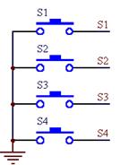
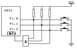
figure 1 figure 2 When the switch S is not pressed, the P1.0 input is high level. After S is closed, the P1.0 input is low level. Since the button is a mechanical contact, there will be jitter when the mechanical contact is opened and closed. The waveform of the P1.0 input is shown in Figure 2. This jitter is imperceptible to humans, but it is completely sensible to computers, because the processing speed of computers is in microseconds, and the mechanical jitter time is at least in milliseconds. For computers, this is a "long" time. Earlier, we talked about a problem when we talked about interrupts, that is, the button sometimes works and sometimes doesn't. In fact, this is the reason. You only pressed the button once, but the computer has executed multiple interrupt processes. If the number of executions is exactly an odd number, then the result is as you expected. If the number of executions is an even number, then it is wrong. In order to enable the CPU to correctly read the state of P1 port and respond only once to each button press, it is necessary to consider how to remove jitter. There are two common ways to remove jitter: hardware method and software method. The software method is commonly used in single-chip microcomputers, so we will not introduce the hardware method. The software method is actually very simple. After the single-chip microcomputer obtains the information that P1.0 port is low, it does not immediately determine that S1 has been pressed, but delays 10 milliseconds or longer to detect P1.0 port again. If it is still low, it means that S1 is indeed pressed. This actually avoids the jitter time when the button is pressed. After detecting that the button is released (P1.0 is high), it delays another 5-10 milliseconds to eliminate the jitter of the trailing edge, and then processes the key value. However, in general, we often do not process the trailing edge of the button release. Practice has proved that it can also meet certain requirements. Of course, in actual applications, the requirements for buttons are also very different, and the processing program should be compiled according to different needs, but the above is the principle of eliminating key jitter. Connection between keyboard and microcontroller image 3 Figure 4 1. Connect through the 1/0 port. Connect one end of each button to the I/O port of the microcontroller and the other end to the ground. This is the simplest way. Figure 3 shows the connection method of the buttons on the experimental board. The four buttons are connected to P3.2, P3.3, P3.4 and P3.5 respectively. For this kind of key, each program can use the method of continuous query. The function is to detect whether there is a key closed. If there is a key closed, remove the key jitter, determine the key number and transfer to the corresponding key processing. A routine is given below. Its function is very simple. The four keys are defined as follows: P3.2: Start, press this button and the lights will start to flow (from top to bottom) P3.3: Stop. Press this button to stop the flow and all lights will be off. P3.4: Up, press this button and the light will flow from top to bottom P3.5: Down, press this button and the light will flow from bottom to top UpDown EQU 00H ; Up and down flag StartEnd EQU 01H ; Start and stop flag LAMPCODE EQU 21H ;Store the flow data code ORG 0000H AJMP MAIN ORG 30H MAIN: MOV SP,#5FH MOV P1,#0FFH CLR UpDown ; Starts in the upward state CLR StartEnd ;Start in stopped state MOV LAMPCODE,#0FEH ; Single lamp flow code LOOP: ACALL KEY ;Call keyboard program JNB F0,LNEXT ;If no key is pressed, continue ACALL KEYPROC ; otherwise call the keyboard handler LNEXT: ACALL LAMP; Call the lamp display program AJMP LOOP; Repeated loop, the main program ends here DELAY: MOV R7,#100 D1: MOV R6,#100 DJNZ R6,$ DJNZ R7,D1 RET ;----------------------------------------Delay program, called during keyboard processing KEYPROC: MOV A,B ; Get the key value from register B JB ACC.2,KeyStart; Analyze the key code. If a bit is pressed, the bit is 1 (because it has been inverted in the keyboard program) JB ACC.3,KeyOver JB ACC.4,KeyUp JB ACC.5,KeyDown AJMP KEY_RET KeyStart: SETB StartEnd ; Processing after the first key is pressed AJMP KEY_RET KeyOver: CLR StartEnd ; Processing after the second key is pressed AJMP KEY_RET KeyUp: SETB UpDown ; Processing after the third key is pressed AJMP KEY_RET KeyDown: CLR UpDown ; Processing after the fourth key is pressed KEY_RET:RET KEY: CLR F0; Clear F0, indicating that no key is pressed. ORL P3,#00111100B ; Set the four bits connected to the key of port P3 to 1 MOV A,P3; Get the value of P3 ORL A,#11000011B ; Set the remaining 4 positions to 1 CPL A ; Negate JZ K_RET ; if it is 0, no key is pressed ACALL DELAY; otherwise delay to remove key jitter ORL P3,#00111100B MOV A,P3 ORL A,#11000011B CPL A JZ K_RET MOV B,A ; If a key is pressed, store the key value in B SETB F0 ; Set the key pressed flag K_RET: ORL P3,#00111100B ; This loop waits for the key to be released MOV A,P3 ORL A,#11000011B CPL A JZ K_RET1 ; Return from the keyboard processing program until the read data is inverted and becomes 0, indicating that the key has been released AJMP K_RET K_RET1: RET D500MS: ;Delay time of running light PUSH PSW SETB RS0 MOV R7,#200 D51: MOV R6,#250 D52: NOP NOP NOP NOP DJNZ R6,D52 DJNZ R7,D51 POP PSW RET LAMP: JB StartEnd, LampStart ; If StartEnd=1, start MOV P1,#0FFH AJMP LAMPRET ; otherwise close all displays and return LampStart: JB UpDown, LAMPUP; If UpDown=1, flow upward MOV A,LAMPCODE RL A; Actually it is just a left shift MOV LAMPCODE,A MOV P1,A LCALL D500MS AJMP LAMPRET LAMPUP: MOV A,LAMPCODE RR A; Flowing downward is actually moving right MOV LAMPCODE,A MOV P1,A LCALL D500MS LAMPRET: RET END The above program function is very simple, but it demonstrates the basic idea of a single-chip keyboard processing program. The program itself is very simple and not very practical. There are many factors to consider in actual work. For example, the main loop calls the light loop program every time, which will cause the button to respond "sluggishly". If you keep pressing the key, the light will not flow until you release it, and so on. You can consider these issues carefully and think about whether there is a good solution. 2. Use interrupt mode: as shown in Figure 4. Each button is connected to an AND gate. When any button is pressed, the AND gate output is low, causing the microcontroller to interrupt. Its advantage is that there is no need to continuously query in the main program. If a key is pressed, the microcontroller will do the corresponding processing. 


Previous article:Lesson 24: Dynamic scanning display interface circuit and program
Next article:Lesson 26: Matrix keyboard interface technology and program design
Recommended ReadingLatest update time:2024-11-16 14:43


- Popular Resources
- Popular amplifiers
-
 Wireless Sensor Network Technology and Applications (Edited by Mou Si, Yin Hong, and Su Xing)
 -
 Modern Electronic Technology Training Course (Edited by Yao Youfeng)
 -
 Modern arc welding power supply and its control
 -
 Small AC Servo Motor Control Circuit Design (by Masaru Ishijima; translated by Xue Liang and Zhu Jianjun, by Masaru Ishijima, Xue Liang, and Zhu Jianjun)
 Professor at Beihang University, dedicated to promoting microcontrollers and embedded systems for over 20 years.
- Innolux's intelligent steer-by-wire solution makes cars smarter and safer
- 8051 MCU - Parity Check
- How to efficiently balance the sensitivity of tactile sensing interfaces
- What should I do if the servo motor shakes? What causes the servo motor to shake quickly?
- 【Brushless Motor】Analysis of three-phase BLDC motor and sharing of two popular development boards
- Midea Industrial Technology's subsidiaries Clou Electronics and Hekang New Energy jointly appeared at the Munich Battery Energy Storage Exhibition and Solar Energy Exhibition
- Guoxin Sichen | Application of ferroelectric memory PB85RS2MC in power battery management, with a capacity of 2M
- Analysis of common faults of frequency converter
- In a head-on competition with Qualcomm, what kind of cockpit products has Intel come up with?
- Dalian Rongke's all-vanadium liquid flow battery energy storage equipment industrialization project has entered the sprint stage before production
- Allegro MicroSystems Introduces Advanced Magnetic and Inductive Position Sensing Solutions at Electronica 2024
- Car key in the left hand, liveness detection radar in the right hand, UWB is imperative for cars!
- After a decade of rapid development, domestic CIS has entered the market
- Aegis Dagger Battery + Thor EM-i Super Hybrid, Geely New Energy has thrown out two "king bombs"
- A brief discussion on functional safety - fault, error, and failure
- In the smart car 2.0 cycle, these core industry chains are facing major opportunities!
- The United States and Japan are developing new batteries. CATL faces challenges? How should China's new energy battery industry respond?
- Murata launches high-precision 6-axis inertial sensor for automobiles
- Ford patents pre-charge alarm to help save costs and respond to emergencies
- New real-time microcontroller system from Texas Instruments enables smarter processing in automotive and industrial applications
- RFID
- Basketball Countdown Case
- Thoughts on White Snake: Origin
- Design a simple low-frequency signal source based on the digital-to-analog conversion chip MAX515
- How to do efficient C programming under ARM?
- Can the simulation be successful when using UC3842 as a non-isolated buck without a floating ground driver?
- GD32E231 DIY Part 1: Unboxing
- Analysis of I2C communication protocol and GPIO simulation in C2000
- Crystal Oscillator Accuracy PPM
- Solution to debugging DAbt_Handler problem

 Wireless Sensor Network Technology and Applications (Edited by Mou Si, Yin Hong, and Su Xing)


 京公网安备 11010802033920号