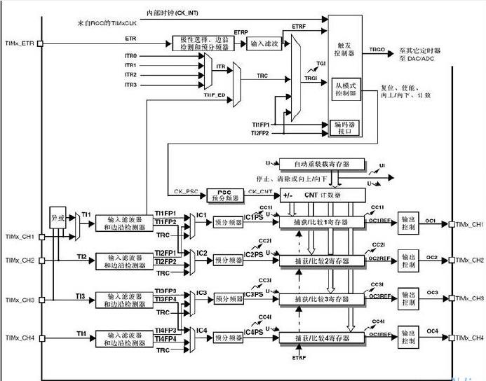
Except for TIM6 and TIM7, all other timers in stm32 have input capture function. This mode is usually used in the calculation of input signal frequency, duty cycle, high and low pulse width, and has a wide range of uses.
STM32 input capture, in simple terms, detects the edge signal on TIMx_CHx, and when the edge signal changes (such as rising edge/falling edge), stores the current timer value (TIMx_CNT) in the capture/compare register (TIMx_CCRx) of the corresponding channel to complete a capture. At the same time, you can also configure whether to trigger interrupt/DMA during capture.
PWM mode capture method: Use TIM3_CH1 as PWM output, TIM2_CH2 to capture the above PWM signal, and measure the frequency and duty cycle. Set the PWM frequency to 1KHz and the duty cycle to 50%.
Specific steps:
1. In order to realize PWM input capture, TIM2 occupies 2 channels. The level change of the second channel will be detected by the first channel and the second channel pins, where the first channel is set to slave mode (how to quickly distinguish the master-slave mode, the rule is as follows: if the second channel is set as PWM input capture, the remaining first channels are slaves, and vice versa).
2. Assuming that the input PWM starts to jump from a low level, when the first rising edge arrives, channels 1 and 2 detect the rising edge at the same time. The slave is set to reset mode, so the count value of TIM2 is reset to 0, and no interrupt request is generated at this time.
3. The next level to arrive is a falling edge. At this time, a capture event occurs in channel 1, and the count value is stored in CCR1 of channel 1.
4. Then, when the second rising edge arrives, a capture event occurs in channel 2, and the count value at this time is stored in CCR2 of channel 2. The reset mode resets the TIM2 count value to 0 at this time, waiting for the second falling edge to arrive.
5. Once the capture process is completed, the PWM frequency f=72M/CCR2; duty cycle: duty=(CCR1/CCR2) X100%
Note: 
In PWM input mode, two channels are used (usually TIMx_CH1 or TIMx_CH2). Only one of the channels can be assigned a gpio clock, and the other is used internally. After assigning a gpio clock to one channel, the other needs to be set as a slave and reset mode. (For example, if ch2 is used, ch1 must be set to slave mode). When an input signal (TI1 or TI2) comes, the master channel captures the rising edge and the slave captures the falling edge.
In the CH2 channel:
TI2FP1 and TI2FP2 are both derived from the edge detection of the same signal TI2. The signals are the same, and the same TIx input maps two ICx signals.
TI2FP1 and TI2FP2 can be set to rising edge or falling edge trigger by the control register corresponding to the connected ICx (IC1 or IC2), and the two ICx signals are valid on opposite polarity edges. If TI2FP2 is set to rising edge trigger, TI2FP1 is set to falling edge trigger, and the two have opposite polarities.
CH1,3,4 are the same.
Specific procedure:
include "pbdata.h"
void RCC_Configuration(void);
void GPIO_Configuration(void);
void NVIC_Configuration(void);
void TIM2_Configuration(void);
void TIM3_Configuration(void);
void USART_Configuration(void);
int fputc(int ch,FILE *f)
{
USART_SendData(USART1,(u8)ch);
while(USART_GetFlagStatus(USART1,USART_FLAG_TXE)==RESET);
return ch;
}
int main(void)
{
RCC_Configuration(); //Configure clock
GPIO_Configuration(); //IO port configuration
TIM3_Configuration();
TIM2_Configuration();
NVIC_Configuration();
USART_Configuration();
while(1)
{
if(flag==1)
{
flag=0;
printf(“the duty is %d/r/n”,duty);
printf(“the frequency is %.2fKHz /r/n”,freq);
}
}
}
void RCC_Configuration(void)
{
SystemInit();
RCC_APB2PeriphClockCmd(RCC_APB2Periph_GPIOA|RCC_APB2Periph_USART1,ENABLE);
RCC_APB1PeriphClockCmd(RCC_APB1Periph_TIM2|RCC_APB1Periph_TIM3,ENABLE);
RCC_APB2PeriphClockCmd(RCC_APB2Periph_AFIO,ENABLE);
}
void GPIO_Configuration(void)
{
GPIO_InitTypeDef GPIO_InitStructure;
//LED
GPIO_InitStructure.GPIO_Pin=GPIO_Pin_9;//TX
GPIO_InitStructure.GPIO_Speed=GPIO_Speed_50MHz;
GPIO_InitStructure.GPIO_Mode=GPIO_Mode_AF_PP;
GPIO_Init(GPIOA,&GPIO_InitStructure);
GPIO_InitStructure.GPIO_Pin=GPIO_Pin_10;//RX
GPIO_InitStructure.GPIO_Mode=GPIO_Mode_IN_FLOATING;
GPIO_Init(GPIOA,&GPIO_InitStructure);
GPIO_InitStructure.GPIO_Pin=GPIO_Pin_6;//PWM,TIM3_CH1
GPIO_InitStructure.GPIO_Speed=GPIO_Speed_50MHz;
GPIO_InitStructure.GPIO_Mode=GPIO_Mode_AF_PP;
GPIO_Init(GPIOA,&GPIO_InitStructure);
GPIO_InitStructure.GPIO_Pin=GPIO_Pin_1;//TIM2_CH2
GPIO_InitStructure.GPIO_Mode=GPIO_Mode_IN_FLOATING;
GPIO_Init(GPIOA,&GPIO_InitStructure);
}
void TIM2_Configuration(void)
{
TIM_TimeBaseInitTypeDef TIM_TimeBaseStruct;
TIM_ICInitTypeDef TIM_ICInitStructure;
TIM_ICInitStructure.TIM_Channel=TIM_Channel_2; //Select TIM2_CH2, select input IC2 and map it to TI2
TIM_ICInitStructure.TIM_ICPolarity=TIM_ICPolarity_Rising; //Rising edge capture
TIM_ICInitStructure.TIM_ICSelection=TIM_ICSelection_DirectTI; //Map to TI2
TIM_ICInitStructure.TIM_ICPrescaler=TIM_ICPSC_DIV1; //Perform a capture each time an edge is detected on the capture input
TIM_ICInitStructure.TIM_ICFilter=0; //Filter setting, after several cycles of jumps, determine that the waveform is stable. (Sampling high level, it is considered valid only when N levels are continuously collected as high levels, otherwise it is considered invalid when it is less than N, N is 0x0-0xF)
TIM_PWMIConfig(TIM2,&TIM_ICInitStructure);//The above is the input capture configuration
TIM_SelectInputTrigger(TIM2,TIM_TS_TI2FP2);//Select the filtered TI2FP2 input as the trigger source to trigger the reset of the following program
TIM_SelectSlaveMode(TIM2,TIM_SlaveMode_Reset);//The slave mode controller is set to reset mode - the rising edge of the selected trigger signal reinitializes the counter and generates an update signal (once the rising edge arrives, TIM2->CNT is cleared, and CNT will be cleared every time the rising edge arrives)
TIM_SelectMasterSlaveMode(TIM2,TIM_MasterSlaveMode_Enable);//Start passive triggering of timer
TIM_ITConfig(TIM2,TIM_IT_CC2,ENABLE);//Capture interrupt on
TIM_ClearFlag(TIM2,TIM_IT_CC2);//Clear flag
TIM_Cmd(TIM2,ENABLE);//Enable timer 2
}
void TIM3_Configuration(void)
{
TIM_TimeBaseInitTypeDef TIM_TimeBaseStruct;
TIM_OCInitTypeDef TIM_OCInitStructure;
TIM_TimeBaseStruct.TIM_Period=72000;//Counting initial value
TIM_TimeBaseStruct.TIM_Prescaler=0;//Frequency division coefficient
TIM_TimeBaseStruct.TIM_ClockDivision=0;//Clock division
TIM_TimeBaseStruct.TIM_CounterMode=TIM_CounterMode_Up;//Upward counting mode
TIM_TimeBaseInit(TIM3,&TIM_TimeBaseStruct);
//TIM3_CH1作为pwm输出
TIM_OCInitStructure.TIM_OCMode=TIM_OCMode_PWM1;
TIM_OCInitStructure.TIM_OutputState=TIM_OutputState_Enable;
TIM_OCInitStructure.TIM_Pulse=36000;
TIM_OCInitStructure.TIM_OCPolarity=TIM_OCPolarity_High;
TIM_OC1Init(TIM3,&TIM_OCInitStructure);
TIM_OC1PreloadConfig(TIM3,TIM_OCPreload_Enable);
TIM_ARRPreloadConfig(TIM3,ENABLE);
TIM_Cmd(TIM3,ENABLE);
}
void NVIC_Configuration(void)
{
NVIC_InitTypeDef NVIC_InitStructure;
NVIC_PriorityGroupConfig(NVIC_PriorityGroup_1);
NVIC_InitStructure.NVIC_IRQChannel = TIM2_IRQn;
NVIC_InitStructure.NVIC_IRQChannelPreemptionPriority = 0;
NVIC_InitStructure.NVIC_IRQChannelSubPriority = 1;
NVIC_InitStructure.NVIC_IRQChannelCmd = ENABLE;
NVIC_Init(&NVIC_InitStructure);
}
void USART_Configuration(void)
{
USART_InitTypeDef USART_InitStructure;
USART_InitStructure.USART_BaudRate=115200;
USART_InitStructure.USART_WordLength=USART_WordLength_8b;
USART_InitStructure.USART_StopBits=USART_StopBits_1;
USART_InitStructure.USART_Parity=USART_Parity_No;
USART_InitStructure.USART_HardwareFlowControl=USART_HardwareFlowControl_None;
USART_InitStructure.USART_Mode=USART_Mode_Rx|USART_Mode_Tx;
USART_Init(USART1,&USART_InitStructure);
USART_Cmd(USART1,ENABLE);
USART_ClearFlag(USART1,USART_FLAG_TC);
}
//中断程序
void TIM2_IRQHandler(void)
{
if(TIM_GetITStatus(TIM2,TIM_IT_CC2)==Bit_SET)
{
float IC2Value=0;
float DutyCycle=0;
float Frequency=0;
float pulse=0;
IC2Value=TIM_GetCapture2(TIM2);//Get the value of CCR2
pulse=TIM_GetCapture1(TIM2);//Get the value of CCR1
DutyCycle=pulse/IC2Value;
Frequency=72000000/IC2Value;
duty=(u32)(DutyCycle*100);
freq=(Frequency/1000);
flag=1;
TIM_ClearITPendingBit(TIM2,TIM_IT_CC2);
}
}
Duty and freq are defined global variables
extern u32 duty;
extern u16 freq;
u32 duty=0;
u16 freq=0;
The program is available after debugging. The frequency and duty cycle are correct. The frequency should not be set too high, because the printf function takes a long time to send data. If the time interval between two captures is short, printf may not send data in time, causing the data to be refreshed. Change the method and use: USART_SendData(); function to send data.
Other applications:
1. Measure the high level time: a. The CCR1 mentioned above is the high level time; b. When using a channel CH1, first select the trigger edge as the rising edge, generate a capture interrupt, read the content in CCR1, and then change the trigger edge to the falling edge. When the falling edge arrives, capture and read the content of CCR1 again. The two times are subtracted to get the high level time.
2. Measure the number of pulses: a. Enable the capture interrupt of timer 1, capture the edge of the signal (rising or falling edge) to interrupt, count++ count, then enable the update interrupt of timer 2, set a certain time to update interrupt, read the count value, which is the number of pulses. b. Enable the external interrupt, configure the edge trigger interrupt, count++ count, then enable the update interrupt of timer x, set a certain time to update interrupt, read the count value, which is the number of pulses.
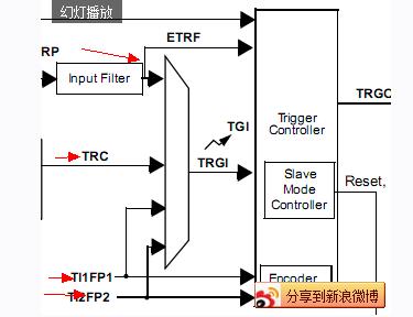
3. To calculate the frequency of one signal, you can select CH1 or CH2 of the timer (you cannot calculate the frequencies of two channels at the same time, otherwise the calculated frequency is the frequency of the signal represented by the channel that is initialized later. Of course, you can also do it at the same time. After each frequency is obtained, switch the channel and take the data through DMA), use PWM input capture mode, and use rising edge trigger. However, this is not possible for CH3 and CH4 channels. As shown in Figure 2, only the 4 signals indicated by the red line are connected to the slave mode controller. Therefore, for channels 3 and 4, the counter value cannot be reset when the rising edge of the signal is received.
Previous article:STM32+MS5611 detailed routine for measuring air pressure and temperature, test correct
Next article:STM32 TIM1 PWM output problem
Recommended ReadingLatest update time:2024-11-16 14:47


 Professor at Beihang University, dedicated to promoting microcontrollers and embedded systems for over 20 years.
- Innolux's intelligent steer-by-wire solution makes cars smarter and safer
- 8051 MCU - Parity Check
- How to efficiently balance the sensitivity of tactile sensing interfaces
- What should I do if the servo motor shakes? What causes the servo motor to shake quickly?
- 【Brushless Motor】Analysis of three-phase BLDC motor and sharing of two popular development boards
- Midea Industrial Technology's subsidiaries Clou Electronics and Hekang New Energy jointly appeared at the Munich Battery Energy Storage Exhibition and Solar Energy Exhibition
- Guoxin Sichen | Application of ferroelectric memory PB85RS2MC in power battery management, with a capacity of 2M
- Analysis of common faults of frequency converter
- In a head-on competition with Qualcomm, what kind of cockpit products has Intel come up with?
- Dalian Rongke's all-vanadium liquid flow battery energy storage equipment industrialization project has entered the sprint stage before production
- Allegro MicroSystems Introduces Advanced Magnetic and Inductive Position Sensing Solutions at Electronica 2024
- Car key in the left hand, liveness detection radar in the right hand, UWB is imperative for cars!
- After a decade of rapid development, domestic CIS has entered the market
- Aegis Dagger Battery + Thor EM-i Super Hybrid, Geely New Energy has thrown out two "king bombs"
- A brief discussion on functional safety - fault, error, and failure
- In the smart car 2.0 cycle, these core industry chains are facing major opportunities!
- The United States and Japan are developing new batteries. CATL faces challenges? How should China's new energy battery industry respond?
- Murata launches high-precision 6-axis inertial sensor for automobiles
- Ford patents pre-charge alarm to help save costs and respond to emergencies
- New real-time microcontroller system from Texas Instruments enables smarter processing in automotive and industrial applications
- Serial port baud rate selection
- STM32 interrupt priority grouping setting
- FreeRtos blocking issue discussion
- Received the X-NUCLEO-IKS01A3 sensor kit
- MSP430 MCU Development Record (20)
- Burning problem
- CH549EVT development board test - running light test
- 5G is coming, small base stations are welcoming development opportunities
- EEWORLD University Hall ---- 2019 National College Student Electronic Design Competition Explanation and Display
- With these experiences, novices can easily choose MOSFET


 西门子S7-12001500 PLC SCL语言编程从入门到精通 (北岛李工)
 usb_host_device_code


 京公网安备 11010802033920号