1. Clock Tree
For ordinary MCUs, you can use them as long as you configure the GPIO registers. In order to achieve low power consumption, STM32 has designed a very complex clock system, and the peripheral clock must be turned on to use peripheral resources.
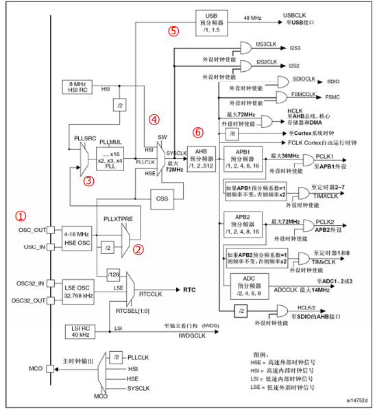
Starting from the left, the clock source is distributed to the peripheral clock step by step.
In terms of clock frequency, it is divided into high-speed clock and low-speed clock. The high-speed clock is the main clock provided to the chip body, while the low-speed clock is only provided to the RTC (real-time clock) and independent watchdog in the chip.
From the chip perspective, the clock source is divided into internal clock and external clock source. The internal clock is generated by the RC oscillator inside the chip, which starts oscillating quickly, so when the chip is just powered on, the clock uses the internal high-speed clock by default. The external clock signal is input by an external crystal oscillator, which has great advantages in accuracy and stability, so after powering on, we use software configuration to switch to the external clock signal.
2. 4 clock sources
High-speed external clock (HSE): Use an external crystal oscillator as the clock source. The crystal oscillator frequency can range from 4 to 16 MHz. We generally use an 8 MHz crystal oscillator.
High-speed internal clock (HSI): Generated by the internal RC oscillator, the frequency is 8MHz, but it is unstable.
Low-speed external clock (LSE): uses an external crystal oscillator as the clock source, mainly provided to the real-time clock module, so 32.768KHz is generally used.
Low-speed internal clock (LSI): generated by the internal RC oscillator and mainly provided to the real-time clock module, with a frequency of about 40KHz.
3. High-speed external clock HSE analysis (8M)
1. Starting from OSC_OUT and OSC_IN on the left, these two pins are connected to the two ends of the external crystal oscillator respectively.
2. The 8MHz clock encounters the first divider PLLXTPRE (HSEdivider for PLLentry). In this divider, you can select its output through register configuration. Its output clock can be a 2-way divider of the input clock or no divider. We choose no divider, so after passing through PLLXTPRE, it is still an 8MHz clock.
3. The 8MHz clock encounters the switch PLLSRC (PLL entryclock source), and we can choose its output, the output is the external high-speed clock (HSE) or the internal high-speed clock (HSI). Here we choose to output HSE, and then encounter the phase-locked loop PLL, which has a frequency multiplication function. Here we can enter the frequency multiplication factor PLLMUL (PLLmultiplicationfactor). The clock passing through the PLL is called PLLCLK. We set the frequency multiplication factor to 9 times, that is, after passing through the PLL, our clock changes from the original 8MHz HSE to 72MHz.
4. Then we encounter a switch SW, after which comes the system clock (SYSCLK) of STM32. Through this switch, we can switch the clock source of SYSCLK, which can be HSI, PLLCLK, HSE. We choose PLLCLK clock, so SYSCLK is 72MHz.
5. Before PLLCLK is input to SW, it also flows to the USB pre-divider, and the output of this pre-divider is the clock (USBCLK) of the USB peripheral.
6. Back to SYSCLK, SYSCLK passes through the AHB pre-divider, and is input to other peripherals after frequency division. For example, it is output to the clocks called HCLK and FCLK, and is also directly output to the SDIOCLK clock of the SDIO peripheral, the FSMCCLK clock of the memory controller FSMC, and the input of the pre-divider of APB1 and APB2. Set the AHB pre-divider to no frequency division, that is, the output frequency is 72MHz.
7. The GPIO peripheral is mounted on the APB2 bus. The clock of APB2 is the output of the APB2 pre-divider, and the clock source of the APB2 pre-divider is the AHB pre-divider. Therefore, if the APB2 pre-divider is set to no frequency division, then we can get the clock of the GPIO peripheral is also equal to HCLK.
四、HCLK、 FCLK、 PCLK1、 PCLK2
SYSCLK: System clock, the clock source of most STM32 devices. Mainly distributed to various components by AHB prescaler.
HCLK: It is directly output by the AHB prescaler. It is the clock signal of the high-speed bus AHB and is provided to the memory, DMA and cortex core. It is the clock for the cortex core to run. The CPU main frequency is this signal. Its size is closely related to the STM32 computing speed and data access speed.
FCLK: Also obtained from the AHB prescaler output, it is the "free running clock" of the core. "Free" means that it does not come from the clock HCLK, so FCLK continues to run when the HCLK clock stops. Its existence can ensure that when the processor is in sleep mode, it can also sample and interrupt and track sleep events.
PCLK1: Peripheral clock, obtained by the APB1 prescaler output, with a maximum frequency of 36MHz, provided to peripherals mounted on the APB1 bus.
PCLK2: Peripheral clock, obtained by the output of the APB2 predivider, with a maximum frequency of 72MHz, provided to peripherals mounted on the APB2 bus.
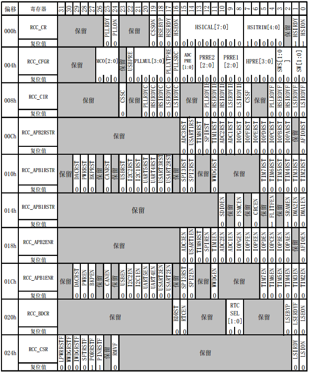
5. Register
//=================================================================
typedef struct
{
__IO uint32_t CR; // Clock control register
__IO uint32_t CFGR; // Clock configuration register
__IO uint32_t CIR; // Clock interrupt register
__IO uint32_t APB2RSTR; // APB2 peripheral reset register
__IO uint32_t APB1RSTR; //APB1 peripheral reset register
__IO uint32_t AHBENR; // AHB peripheral clock enable register
__IO uint32_t APB2ENR; // APB2 peripheral clock enable register
__IO uint32_t APB1ENR; // APB1 peripheral clock enable register
__IO uint32_t BDCR; // Backup domain control register
__IO uint32_t CSR; // Control/Status Register
#ifdefSTM32F10X_CL
__IO uint32_t AHBRSTR;
__IO uint32_t CFGR2;
#endif/* STM32F10X_CL */
#if defined (STM32F10X_LD_VL) || defined (STM32F10X_MD_VL) || defined(STM32F10X_HD_VL)
uint32_t RESERVED0;
__IO uint32_t CFGR2;
#endif/* STM32F10X_LD_VL || STM32F10X_MD_VL || STM32F10X_HD_VL */
} RCC_TypeDef;
#define CRC_BASE (AHBPERIPH_BASE +0x3000)
#define RCC ((RCC_TypeDef *)RCC_BASE)
voidRCC_APB2PeriphClockCmd(uint32_t RCC_APB2Periph, FunctionalState NewState)
{
/* Check the parameters */
assert_param(IS_RCC_APB2_PERIPH(RCC_APB2Periph));
assert_param(IS_FUNCTIONAL_STATE(NewState));
if (NewState != DISABLE)
{
RCC->APB2ENR |= RCC_APB2Periph;
}
else
{
RCC->APB2ENR &= ~RCC_APB2Periph;
}
}
Previous article:Cortex M3 Register Set
Next article:Detailed explanation of STM32 startup file - startup_stm32f10x_xx.s
Recommended ReadingLatest update time:2024-11-16 14:49

![[STM32 Motor Vector Control] Record 8——ADC Three-Resistor Sampling](https://6.eewimg.cn/news/statics/images/loading.gif)


- Popular Resources
- Popular amplifiers
 Professor at Beihang University, dedicated to promoting microcontrollers and embedded systems for over 20 years.
- Innolux's intelligent steer-by-wire solution makes cars smarter and safer
- 8051 MCU - Parity Check
- How to efficiently balance the sensitivity of tactile sensing interfaces
- What should I do if the servo motor shakes? What causes the servo motor to shake quickly?
- 【Brushless Motor】Analysis of three-phase BLDC motor and sharing of two popular development boards
- Midea Industrial Technology's subsidiaries Clou Electronics and Hekang New Energy jointly appeared at the Munich Battery Energy Storage Exhibition and Solar Energy Exhibition
- Guoxin Sichen | Application of ferroelectric memory PB85RS2MC in power battery management, with a capacity of 2M
- Analysis of common faults of frequency converter
- In a head-on competition with Qualcomm, what kind of cockpit products has Intel come up with?
- Dalian Rongke's all-vanadium liquid flow battery energy storage equipment industrialization project has entered the sprint stage before production
- Allegro MicroSystems Introduces Advanced Magnetic and Inductive Position Sensing Solutions at Electronica 2024
- Car key in the left hand, liveness detection radar in the right hand, UWB is imperative for cars!
- After a decade of rapid development, domestic CIS has entered the market
- Aegis Dagger Battery + Thor EM-i Super Hybrid, Geely New Energy has thrown out two "king bombs"
- A brief discussion on functional safety - fault, error, and failure
- In the smart car 2.0 cycle, these core industry chains are facing major opportunities!
- The United States and Japan are developing new batteries. CATL faces challenges? How should China's new energy battery industry respond?
- Murata launches high-precision 6-axis inertial sensor for automobiles
- Ford patents pre-charge alarm to help save costs and respond to emergencies
- New real-time microcontroller system from Texas Instruments enables smarter processing in automotive and industrial applications
- MSP430 capture device is simple and practical
- I want to learn stm32, please recommend a tutorial
- [NXP Rapid IoT Review] + Use of Bluetooth (1 Preliminary Exploration)
- 500 yuan for infrared counting microcontroller
- Why can the serial port receive 9600 but lose bytes at 115200?
- What is the chip with 4BMN silk screen? It has 5 pins.
- I encountered a problem when testing the CAN communication isolation chip a few days ago. I hope you can give me some advice.
- Reminiscing about the past! A brief discussion on the century-long history of radio development
- Network port debugging issues
- I bought a few gold-sealed transistors on Taobao. The silk screen can be wiped off with bare hands.


 usb_host_device_code
 Transplantation of real-time operating system RT-ThreadSmart on STM32MP1


 京公网安备 11010802033920号