Note:
1.ROM: Read-only memory. The read-only storage area of the microcontroller is mostly used to store program memory, also known as program memory.
The 51 single-chip microcomputer is an EPROM, which is an erasable read-only memory. The original program can be erased and a new one can be written in.
The data can be saved after power failure, but the data memory (RAM) cannot be saved.
RAM can only store defined variables continuously when the program is executed. For example, int x, int y
You can use the code instruction to put the defined variables in ROM instead of RAM, saving RAM resources
2. RAM: Random Access Memory, used to store defined variables, etc., fast
The RAM storage capacity of the 51 microcontroller is much smaller than the ROM, but the speed is very fast.
Detailed interior illustration

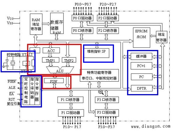
The internal structure looks very complicated, but it can be roughly divided into two parts: the operator (red box) and the controller (blue box).
Arithmetic unit: Its main function is to perform addition, subtraction, multiplication, division and logical operations.
The internal structure can be found online.Controller: controls various operations of the microcontroller
Program execution process
1. Program address
When the program starts, the address of the first program must be known first, which is known through PC (Program Counter).
For example, at the beginning, the address is 0000H, which is hexadecimal.
When this address is sent to the address register, that is, after the first instruction is taken out, PC automatically increases by 1, ready to take out the next instruction.
2.
After knowing the address of the instruction by reading the address register, it takes out an instruction pointed to by the address from the ROM (read-only memory).
And puts the fetched instruction into the instruction register, and compiles it through the instruction encoder.
3. Data processing
instructions may require addition, subtraction, multiplication, division and assignment statements. After the instruction encoder, we know which defined data or assignment statements to take out.
We retrieve the data we need through the bus and perform calculations through the arithmetic unit.
For example, we define int x and int y, and store these two data in RAM.
When we fetch an instruction a = x + y, we need the values of x and y to calculate.
Then, through the data fetching process in the previous figure, the data of x and y are fetched
and calculated by the arithmetic unit.
As shown in the figure, take out x and y and enter the black box (operator) to get the final result.
The final result will also be stored in the data storage (RAM) through the variable a.
4. Operating device
Of course, in addition to the calculation step, there is also a situation where the high and low levels of the IO port or other devices are directly controlled.
illustrate
The operation process of this microcontroller is obtained by the author after consulting the data, and it is not necessarily correct. If it is not correct, please correct it.
Previous article:LAN control system - lower computer - single chip microcomputer
Next article:MCU 4*4 button digital tube display 0-9
- Popular Resources
- Popular amplifiers
 Professor at Beihang University, dedicated to promoting microcontrollers and embedded systems for over 20 years.
- LED chemical incompatibility test to see which chemicals LEDs can be used with
- Application of ARM9 hardware coprocessor on WinCE embedded motherboard
- What are the key points for selecting rotor flowmeter?
- LM317 high power charger circuit
- A brief analysis of Embest's application and development of embedded medical devices
- Single-phase RC protection circuit
- stm32 PVD programmable voltage monitor
- Introduction and measurement of edge trigger and level trigger of 51 single chip microcomputer
- Improved design of Linux system software shell protection technology
- What to do if the ABB robot protection device stops
- Huawei's Strategic Department Director Gai Gang: The cumulative installed base of open source Euler operating system exceeds 10 million sets
- Download from the Internet--ARM Getting Started Notes
- Learn ARM development(22)
- Learn ARM development(21)
- Learn ARM development(20)
- Learn ARM development(19)
- Learn ARM development(14)
- Learn ARM development(15)
- Analysis of the application of several common contact parts in high-voltage connectors of new energy vehicles
- Wiring harness durability test and contact voltage drop test method
- [Qinheng Trial] Three CH549 uses pwm to adjust the brightness of the lamp
- Gallium nitride killer application: lithium battery protection!
- About C language conditional compilation
- 【National Technology N32G430】LCD-ST7735
- The STM32 video account and B station account have been opened. Are you paying attention?
- 【RT-Thread Reading Notes】Reflections on RT-Thread Chapter 9
- 100% gift for a limited time: Download and share Keysight millimeter wave radar data to win a gift
- About GUI_Init stuck when emwin is ported to stm32f2
- Huawei Static Timing Analysis and Logic Design.pdf
- Where does the TTL on the laser driver board connect to the CNC shield V3 board?


 AM747ADMB


 京公网安备 11010802033920号