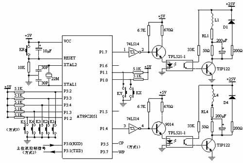
Schematic diagram of stepper motor driver system circuit
AT89C2051 outputs control pulse from P1.4~P1.7 of P1 port, enters 9014 after inversion by 74LS14, controls photoelectric switch after amplification by 9014, and after photoelectric isolation, the pulse signal is amplified by power tube TIP122 for voltage and current amplification to drive each phase winding of the stepper motor. The stepper motor can perform forward, reverse, accelerate, decelerate and stop actions according to different pulse signals. L1 in the figure is a phase winding of the stepper motor. AT89C2051 uses a crystal oscillator with a frequency of 22MHz. The purpose of using a higher crystal oscillator is to minimize the influence of AT89C2051 on the pulse signal cycle of the host computer under mode 2.
RL1~RL4 in the figure are the internal resistance of the winding, and the 50Ω resistor is an external resistor, which plays a current limiting role and is also a component to improve the loop time constant. D1~D4 are freewheeling diodes, which attenuate the back electromotive force generated by the motor winding through the freewheeling diodes (D1~D4), thereby protecting the power tube TIP122 from damage.
A 200μF capacitor is connected in parallel with the 50Ω external resistor to improve the leading edge of the current pulse injected into the stepper motor winding and improve the high-frequency performance of the stepper motor. The 200Ω resistor connected in series with the freewheeling diode can reduce the discharge time constant of the loop, making the trailing edge of the current pulse in the winding steeper and the current falling time shorter, which also plays a role in improving the high-frequency working performance.
Previous article:NRF24l01 Wireless Temperature Sensor (2)
Next article:Smart electric vehicles and drive system circuit design strategy
Recommended ReadingLatest update time:2024-11-16 13:03


- Popular Resources
- Popular amplifiers
-
 Real-time driver monitoring system via modal and viewpoint analysis
 -
 Multi-port and shared memory architecture for high-performance ADAS SoCs
 -
 Computer Vision Applications in Autonomous Vehicles: Methods, Challenges, and Future Directions
 -
 Practical Development of Automotive FlexRay Bus System (Written by Wu Baoxin, Guo Yonghong, Cao Yi, Zhao Dongyang, etc.)
 Professor at Beihang University, dedicated to promoting microcontrollers and embedded systems for over 20 years.
- Innolux's intelligent steer-by-wire solution makes cars smarter and safer
- 8051 MCU - Parity Check
- How to efficiently balance the sensitivity of tactile sensing interfaces
- What should I do if the servo motor shakes? What causes the servo motor to shake quickly?
- 【Brushless Motor】Analysis of three-phase BLDC motor and sharing of two popular development boards
- Midea Industrial Technology's subsidiaries Clou Electronics and Hekang New Energy jointly appeared at the Munich Battery Energy Storage Exhibition and Solar Energy Exhibition
- Guoxin Sichen | Application of ferroelectric memory PB85RS2MC in power battery management, with a capacity of 2M
- Analysis of common faults of frequency converter
- In a head-on competition with Qualcomm, what kind of cockpit products has Intel come up with?
- Dalian Rongke's all-vanadium liquid flow battery energy storage equipment industrialization project has entered the sprint stage before production
- Allegro MicroSystems Introduces Advanced Magnetic and Inductive Position Sensing Solutions at Electronica 2024
- Car key in the left hand, liveness detection radar in the right hand, UWB is imperative for cars!
- After a decade of rapid development, domestic CIS has entered the market
- Aegis Dagger Battery + Thor EM-i Super Hybrid, Geely New Energy has thrown out two "king bombs"
- A brief discussion on functional safety - fault, error, and failure
- In the smart car 2.0 cycle, these core industry chains are facing major opportunities!
- The United States and Japan are developing new batteries. CATL faces challenges? How should China's new energy battery industry respond?
- Murata launches high-precision 6-axis inertial sensor for automobiles
- Ford patents pre-charge alarm to help save costs and respond to emergencies
- New real-time microcontroller system from Texas Instruments enables smarter processing in automotive and industrial applications
- A lightweight and precise positioning algorithm based on multiple inertial measurement units (LSM6DSOX)
- PT1000 circuit help
- Brief analysis of the working principle of DSP
- The national competition is tomorrow. What are you doing today?
- Looking for asm330lxh driver!!!
- Share post: Just completed FPGA interpolation filter design
- Introduction to Common PCB Microvia Technology
- Analysis of the design principle of single chip microcomputer music program
- Beetle_ESP32-C3 Arduino routine learning
- [BearPi-HM Nano, play Hongmeng's "touch and pay" function] Part 4: Combination of OLED and UDP!

 Real-time driver monitoring system via modal and viewpoint analysis


 京公网安备 11010802033920号