In a single-chip microcomputer, the relationship between pulse counting and time is very close. Each time a pulse is input, the value of the counter will automatically accumulate by 1, and the time taken is exactly 1 microsecond. As long as the time interval between two adjacent counting pulses is equal, the count value represents the passage of time.
Therefore, the timer and counter in a single-chip microcomputer are actually the same physical electronic component, except that the counter records what happens outside the single-chip microcomputer (it receives external pulses), while the timer is a very stable counter provided by the single-chip microcomputer itself. This stable counter is the crystal oscillator component connected to the single-chip microcomputer. After the crystal oscillator of the MCS-51 single-chip microcomputer is divided by 12, it only provides a stable pulse of 1MHZ to the single-chip microcomputer. The frequency of the crystal oscillator is very accurate, so the time interval between the counting pulses of the single-chip microcomputer is also very accurate, and this accurate time interval is 1 microsecond.
The MCS-51 microcontroller is connected to a 12MHZ crystal oscillator (actually 11.0592MHZ), so the internal operating frequency (clock pulse frequency) of the MCS-51 microcontroller is 12MHZ/12=1MHZ=1000000 times/second=1000000 instructions/second=1000000 times/1000000 microseconds=1 time/microsecond=1 instruction/microsecond; that is, the crystal oscillator oscillates once, it will provide a clock pulse to the microcontroller, and the time spent is 1 microsecond, so When the CPU executes an instruction, it will go through a machine cycle; that is: 1 clock pulse = 1 machine cycle = 1 microsecond = 1 instruction;
Note: The CPU main frequency on a personal PC is the frequency of the crystal oscillator after multiplication, which is exactly the opposite of the MCS-51 microcontroller. The main frequency of the MCS-51 microcontroller is the frequency of the crystal oscillator after division;
In short: The concept of time in the MCS-51 microcontroller is measured by counting the number of pulses; 1 pulse = 1 microsecond = 1 instruction = 1 machine cycle; The
simple structure diagram of the MCS-51 microcontroller timer/counter:

The 8051 series microcontroller has two timers: T0 and T1, respectively called timer and timer T1, both of which are 16-bit timer/counters; the 8052 series microcontroller adds a third timer/counter T2; they all have timing or event counting functions, and are often used in time control, delay, external time counting and detection, etc.;
2. The structure of the timer/counter The
two timers T0 and T1 of the 8051 microcontroller are composed of two special function registers; T0 is composed of special function registers TH0 and TL0, while T1 is composed of TH1 and TL1;
when used as a timer , the timer counts the number of pulses after the 12-division output of the oscillator on the 8051 microcontroller chip, that is: each machine cycle automatically adds 1 to the register value of the timer T0/T1 until it overflows, and then continues to count from 0 after the overflow; therefore, the resolution of the timer is 1/12 of the clock oscillation frequency;
when used as a counter, it counts the external pulse signal through pin T0 (P3.4) or T1 (P3.5), and when the input external pulse signal changes from 1 to 0, the counter value automatically adds 1; the maximum frequency of the counter is generally 1/24 of the clock oscillation frequency;
it can be seen that whether it is a fixed Timer or counter working mode, timer T0 and T1 do not occupy CPU time, unless timer/counter T0 and T1 overflow, it may cause CPU interruption, and then execute interrupt handler; therefore, timer/counter is a high-efficiency and flexible component in single-chip microcomputer;
III. Working mode of timer/counter
In addition to the two working modes of timer and counter, each timer/counter has 4 working modes;
in modes 0, 1 and 2, T0 and T1 have the same working mode; in mode 3, the working modes of the two timers/counters are different;
working mode 0:
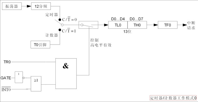
TL0 The lower 5 bits of TH0 and all 8 bits of TH0 together form a 13-bit timer/counter; after the timer/counter is started, the number of timing or counting pulses is added to TL0, starting from the preset initial value (time constant) and increasing by 1; when TL0 is full, it is carried to TH0 until the 13-bit register is full and overflows; when overflowing, the timer/counter hardware will automatically clear the 13-bit register value to 0 and set the interrupt flag TF0 to 1; if further timing/counting is required, the relevant instructions need to be used to reset the time constant and set the interrupt flag TF0 of the timer/counter to 0; the structure of working mode 0 is as follows:
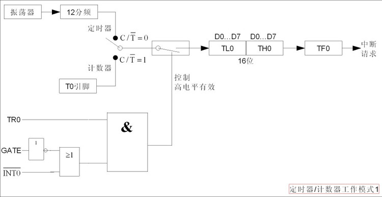
Mode 1 is almost identical to Mode 0, the only difference is that registers TH0 and TL0 in Mode 1 together form a 16-bit timer/counter to participate in the operation, so the timing/counting range is larger than that in Mode 0; the structure of working mode 1 is as follows:
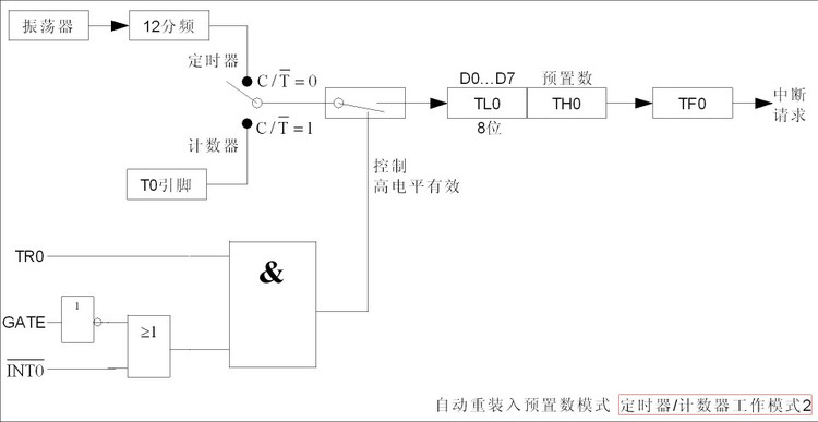
This mode is also called automatic reload preset number mode; when the value of register TH0/TL0 of the timer/counter overflows, the timer/counter hardware device will automatically clear the value of register TH0/TL0 to 0 to restart the operation; but sometimes, our timing/counting operation needs to be repeated many times. If no processing is done when the overflow occurs, then the timing/counting will start from 0 in the second round, which is not what we want; therefore, to ensure that after each overflow, the timing/counting operation is what we want when we restart it, we need to reload the preset number (time constant) into a certain place; and the operation of reloading the preset number is automatically completed by the hardware device, and no manual intervention is required. Therefore, this working mode is It is called automatic reload preset number mode; since the preset number needs to be reloaded, the preset number must be stored somewhere to ensure the success of the reload operation; in working mode 2, the automatically reloaded preset number is stored in the upper 8 bits of the timer/counter register, that is, in TH0, and only TL0 is left to participate in the timing/counting operation; obviously, the timing/counting position is much smaller;
Note: This working mode is often used in baud rate generators (serial communication), T1 works in serial mode 2; when used in this way, the timer is to provide a time base; after the count overflows, there is no need to do too much, just one thing, that is, reload the preset number and start counting again, and no delay is required in the middle; the structure of working mode 2 is as follows:
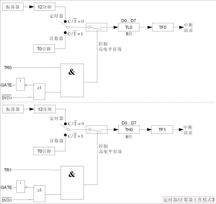
Since timer/counter T1 does not have working mode 3, if timer/counter T0 is set to working mode 3, TL0 and TH0 will be divided into two independent 8-bit timer/counters; the structure of working mode 3 is as follows:
Working mode 0: 13-bit timer/counter working mode, can count up to 2 to the 13th power, that is: 8192 times, [0,8191];
Working mode 1: 16-bit timer/counter working mode, can count up to 2 to the 16th power, that is: 65536 times, [0,65535];
Working mode 2: 8-bit timer/counter working mode, can count up to 2 to the 8th power, that is: 256 times, [0,255];
Working mode 3: 8-bit timer/counter working mode, can count up to 2 to the 8th power, that is: 256 times, [0,255];
Preset number calculation formula: Preset number = maximum value - number of times to be counted;
5. Control register of timer/counter
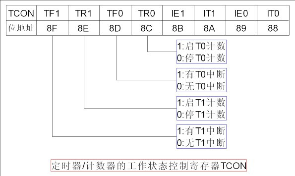
The 8051 microcontroller designs two 8-bit special function registers to control the working state of the timer/counter; these two special function registers are TMOD and TCON; both are in the special function register area;
1. Working mode control register TMOD (89h):
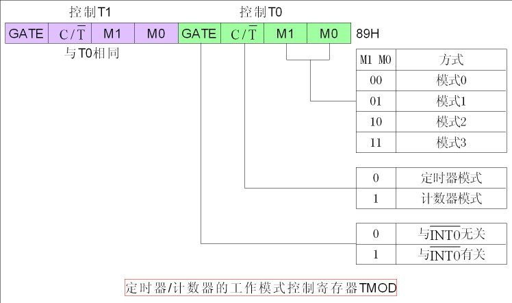
2. Working status control register TCON (88H):
6. Initialization of timer/counter
1. Set the working mode TMOD of timer/counter (mode 1 is commonly used: TMOD=0x01);
2. Load the preset number into THx and TLx (THx=TLx=MAX(8192/65536/256)-counting times);
3. If working in interrupt mode, it is necessary to open the flag bit in the interrupt TCON of the timer/counter: TF0/TF1=0/1;
4. Start the timer/counter: TR0/TR1=1;
Note: Since the clock pulse used by the timer/counter of the 8051 microcontroller is the frequency of the external crystal oscillator (12MHZ) after 12 division (12MHZ/12=1MHZ), one clock pulse is 1 microsecond; therefore, 8192 pulses = 8192 microseconds = 8.192 milliseconds; 65536 pulses = 65536 microseconds = 65.536 milliseconds; 256 pulses = 256 microseconds = 0.256 milliseconds;
Previous article:Design of Arbitrary Waveform Generator Based on CPLD and AT89C52
Next article:MCS-51 single chip microcomputer input and output port
- Popular Resources
- Popular amplifiers
 Professor at Beihang University, dedicated to promoting microcontrollers and embedded systems for over 20 years.
- LED chemical incompatibility test to see which chemicals LEDs can be used with
- Application of ARM9 hardware coprocessor on WinCE embedded motherboard
- What are the key points for selecting rotor flowmeter?
- LM317 high power charger circuit
- A brief analysis of Embest's application and development of embedded medical devices
- Single-phase RC protection circuit
- stm32 PVD programmable voltage monitor
- Introduction and measurement of edge trigger and level trigger of 51 single chip microcomputer
- Improved design of Linux system software shell protection technology
- What to do if the ABB robot protection device stops
- Huawei's Strategic Department Director Gai Gang: The cumulative installed base of open source Euler operating system exceeds 10 million sets
- Download from the Internet--ARM Getting Started Notes
- Learn ARM development(22)
- Learn ARM development(21)
- Learn ARM development(20)
- Learn ARM development(19)
- Learn ARM development(14)
- Learn ARM development(15)
- Analysis of the application of several common contact parts in high-voltage connectors of new energy vehicles
- Wiring harness durability test and contact voltage drop test method
- AltiumDesigner integrated library design based on Access database
- EEWORLD University Hall----Live Replay: TE explains the design trends of smart antennas and sensor application cases in the Internet of Things
- Solution to EPLAN software freeze
- Can the same timer realize two independent PWM pulses?
- Thirty-two channel scanning PCI data acquisition module design.pdf
- Today's live broadcast: ADI inertial MEMS applications
- .DSN file is garbled when opened.
- [ESP32-Korvo Review] 06 Development Environment Construction Part 3 (A History of Blood and Tears)
- How to print data using J-Link RTT in IAR?
- Security Technology System of Wireless WLAN

 5962-8771901EX


 京公网安备 11010802033920号