1 Measuring principle
According to the knowledge of heat transfer, under the pressure of 1.6 Mpa and the temperature range of 0 to 95°C, the density of water is
ρ=1 001.093 78-0.076 73t+0.003 57t2 (1)
Where ρ is the density of water, unit is kg/m3; t is the temperature, unit is ℃.
The enthalpy of water is
h=27.596 1+1.529 19t+0.041 24t2 (2)
Where h is the enthalpy of water, in kJ/kg.
Assume that the outlet temperature of the heat source is t1 and the return temperature is t2. The enthalpy value h1 of the heat source outlet and the enthalpy value h2 of the return can be obtained by formula (2). The enthalpy difference between the heat source outlet and the return is
△h=h1-h2 (3)
The heat output of the heat source is
Q=ρ1△hV (4)
In the formula, Q is the heat output of the heat source, in kJ; V is the output volume of the heat source outlet, in m3.
When measuring heat energy with a heat energy meter, the output volume V at the heat source outlet is usually a fixed value, and V is called the volume flow rate at the heat source outlet.
If the single-chip microcomputer can accurately measure the heat source outlet temperature t1 and the return water temperature t2, as well as the heat source outlet volume flow V, the heat energy measurement can be completed accurately. The single-chip microcomputer also completes various numerical calculations, accumulation, storage, display, and communication with the host computer.
2 System Hardware Design
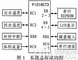
The overall structure diagram of the intelligent thermal energy meter system is shown in Figure 1.

2.1 Microcontroller
The core of the intelligent heat meter is the PIC16C73 microcontroller produced by MICROCHIP. The chip is an 8-bit microcontroller, dual in-line 28-pin package, 192 bytes of RAM, 4K bytes of EPROM, 22 I/O ports, 3 timers/counters, 2 capture inputs/compare outputs/PWM outputs, 2 serial ports can be set to SPI or I2C bus mode, and 5-channel high-speed 8-bit A/D converter. It has built-in power-on reset, power-on timer and oscillator start-up timer, watchdog timer of on-chip RC oscillator, program code protection and power-saving sleep mode. The system composed of PIC16C7 microcontroller can effectively reduce external components, reduce power consumption and cost, and increase system reliability. Once the program runs away, the watchdog will automatically reset the system and the program will be re-executed from the beginning.
2.2 Digital Temperature Measurement Device
Conventional analog temperature measurement requires a series of circuits to complete signal conditioning, amplification, sampling and holding, and A/D conversion. It is costly, requires debugging and calibration, occupies more hardware resources, and has a short measurement distance. The one-bus digital temperature sensor DS18B20 produced by DALLAS has a 3-pin TO-92 small package; the temperature measurement range is -55~+125℃, and it can be programmed to 12-bit A/D conversion accuracy. The temperature measurement resolution can reach 0.062 5℃, and the accuracy is ±0.5℃. The measured temperature is serially output in the form of a 16-bit digital quantity with sign extension; its working power supply can be introduced at the remote end or generated by parasitic power supply; it is simple to connect to the microcontroller, which improves the reliability of the sensor. The measurement distance between the microcontroller and the DS18B20 is related to the inter-wire capacitance of the connecting cable. The common connecting cable has a large inter-wire capacitance, and the digital signal is severely attenuated. The temperature measurement distance is generally within 100 m. After theoretical analysis and practical verification, this device uses three types of twisted pair cables as transmission lines. The twisted structure of the data line can greatly reduce the capacitance between the lines and effectively extend the transmission distance. The effective measurement distance of the temperature sensor of this device can reach 400 m.
2.3 Flow sensor
The volume flow rate of the heat source outlet adopts an adaptive magnet-reed switch sensor, which is also called a "push-pull bistable" structure sensor. It has only two states: disconnected state and attracted state, and there is no gentle buffered self-maintaining transition state. It can greatly reduce external interference such as water hammer phenomenon, avoid counting errors caused by false operation input, and work more stably and measure more accurately.
2.4 Serial E2PROM
The 24C02 produced by ATMEL is selected as the memory. It is an I2C bus serial port E2PROM, containing 2K 8-bit storage units, with high reliability of 100,000 erase/write cycles and 100-year data retention. It is used to store information such as cumulative flow, cumulative heat, operating days, and keyboard setting parameters. The data will not be volatile after power failure. The data stored in the chip can be encrypted by software using encryption algorithms to improve security and expand the application range of the device.
2.5 LCD display
The necessary information is displayed using the LCM08TJY 8-bit 8-character plus segment prompt LCD module. It has built-in display RAM, can display any field strokes, and transmits data via the I2C bus serial port. Low power consumption, wide voltage, adjustable viewing angle contrast, clear display, stable and reliable, and simple to use and program. The accumulated heat, accumulated flow, inlet and return water temperature and temperature difference, and operating days can be displayed cyclically through key control. It comes with 2 kHz and 4 kHz buzzer drivers, which can send out sound alarm signals when the system fails.
2.6 PCF8563 clock chip
This chip is a multifunctional clock/calendar chip with I2C bus and extremely low power consumption launched by PHILIPS. It has 4 alarm functions and timing functions; internal clock circuit, internal oscillation circuit, internal low voltage detection and two-wire I2C bus communication mode, which not only simplifies the peripheral circuit, but also increases the reliability of the chip. This system uses the day alarm function to record the number of days the system is running. With a little modification, it can record the number of running hours, display the current time, etc., further enhancing the system function.
2.7 MAX487 communication chip clock chip
The MAX485 interface chip is a chip from Maxim that can realize RS-485 communication. It is a low-power transceiver used for RS-485 and RS-422 communication. It has a driver and a receiver, and has a slew rate limited driver, which can effectively reduce EMI and reflections caused by improper terminal matching cables, and achieve error-free data transmission at up to 250 kbps. This design uses this chip to upload the real-time data of the heat meter to the computer of the management department.
2.8 System Circuit Diagram
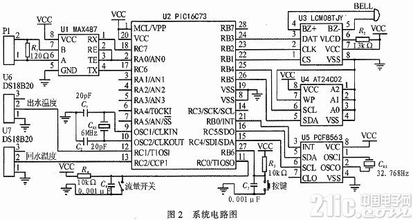
The circuit diagram of the intelligent heat meter system is shown in Figure 2. The buttons are used to activate the LCD display and browse and change the content you want to display.

3 System Software Design
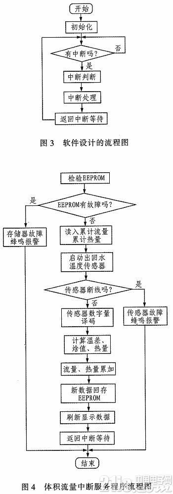
The software consists of a main program, an interrupt service program, and various subroutines. The interrupts include volume flow interrupt, serial port communication interrupt with the host computer, date interrupt, and key interrupt. To facilitate program analysis and use, the system software adopts a structured module programming method, and each module is connected by a subroutine call. In view of the shortcomings of the single-chip microcomputer's weak ability to process floating-point numbers, all data are represented in 24-bit signed numbers, and the absolute value of the representation range can reach 0.5×10-127 to 1×101 28, and the accuracy can reach 2-16. The volume flow rate is dynamically set, and its range can be from 0.1 to 99.9 m3, which greatly expands the measurement range of the heat meter. In order to improve the reliability of the system and ensure that data is not lost under any circumstances, in addition to hardware preventive measures, watchdogs and software traps are used to capture the program "runaway" caused by power supply voltage fluctuations, electromagnetic interference, etc., and lead the program to the error handling program to restore the normal operation of the system. In order to avoid line failures and component failures, the system performs detection every time it reads the temperature sensor and EEPROM. Once a fault occurs, a buzzer alarm and error display will be automatically issued. The main program flow chart of the system is shown in Figure 3. The volume flow interrupt service program flow chart is shown in Figure 4.

4 Conclusion
The intelligent heat energy meter uses a bus-type digital temperature sensor DS18B20 to detect the outlet and return water temperatures, and an adaptive magnet-reed switch sensor to detect the outlet volume flow rate. In addition, the PIC16C73 has a built-in watchdog function and a program self-check function, which greatly improves the reliability, accuracy and stability of the intelligent heat energy meter and is of great practical value.
Previous article:PIC16F877A TIMER1 counting operation
Next article:PWM function of PIC16F877A microcontroller
Recommended ReadingLatest update time:2024-11-16 20:54


- Popular Resources
- Popular amplifiers
-
 MCU C language programming and Proteus simulation technology (Xu Aijun)
 -
 100 Examples of Microcontroller C Language Applications (with CD-ROM, 3rd Edition) (Wang Huiliang, Wang Dongfeng, Dong Guanqiang)
 -
 Single-chip microcomputer technology and application - electronic circuit design, simulation and production (edited by Zhou Runjing)
 -
 Principles and Applications of Single Chip Microcomputers and C51 Programming (3rd Edition) (Xie Weicheng, Yang Jiaguo)
 Professor at Beihang University, dedicated to promoting microcontrollers and embedded systems for over 20 years.
- Innolux's intelligent steer-by-wire solution makes cars smarter and safer
- 8051 MCU - Parity Check
- How to efficiently balance the sensitivity of tactile sensing interfaces
- What should I do if the servo motor shakes? What causes the servo motor to shake quickly?
- 【Brushless Motor】Analysis of three-phase BLDC motor and sharing of two popular development boards
- Midea Industrial Technology's subsidiaries Clou Electronics and Hekang New Energy jointly appeared at the Munich Battery Energy Storage Exhibition and Solar Energy Exhibition
- Guoxin Sichen | Application of ferroelectric memory PB85RS2MC in power battery management, with a capacity of 2M
- Analysis of common faults of frequency converter
- In a head-on competition with Qualcomm, what kind of cockpit products has Intel come up with?
- Dalian Rongke's all-vanadium liquid flow battery energy storage equipment industrialization project has entered the sprint stage before production
- Allegro MicroSystems Introduces Advanced Magnetic and Inductive Position Sensing Solutions at Electronica 2024
- Car key in the left hand, liveness detection radar in the right hand, UWB is imperative for cars!
- After a decade of rapid development, domestic CIS has entered the market
- Aegis Dagger Battery + Thor EM-i Super Hybrid, Geely New Energy has thrown out two "king bombs"
- A brief discussion on functional safety - fault, error, and failure
- In the smart car 2.0 cycle, these core industry chains are facing major opportunities!
- The United States and Japan are developing new batteries. CATL faces challenges? How should China's new energy battery industry respond?
- Murata launches high-precision 6-axis inertial sensor for automobiles
- Ford patents pre-charge alarm to help save costs and respond to emergencies
- New real-time microcontroller system from Texas Instruments enables smarter processing in automotive and industrial applications
- 【Development and application based on NUCLEO-F746ZG motor】13. Parameter configuration - USART3 configuration
- What is the sound-generating mechanism of a piezoelectric buzzer? How to choose the sound component?
- The mechanical and electrical parts of the intelligent car based on the DFRobot four-way motor driver board have been preliminarily completed.
- [Example] Easily implement wifi remote RS485 bus (multi-node bus)
- Talk about the upper and lower tubes of the buck circuit_DC-DC BUCK bootstrap circuit
- Real-time solution to single chip microcomputer delay
- CB5654 Development Board Review 2
- [Raspberry Pi Pico Review] 3. My first project
- Problems with op amp sampling in oximeters
- EasyARM-RT1052 Review Summary

 MCU C language programming and Proteus simulation technology (Xu Aijun)


 京公网安备 11010802033920号