This design is a video surveillance car that can be controlled by an intelligent terminal and can also be monitored in real time by a host computer. In the system developed this time, a local area network is established by using a wireless router and a wireless network card, and an mjpgstreamer network video server is set up in the smart car. At the same time, the smart car is connected to the established local area network through a wireless network card. The client can be used on a PC for real-time monitoring and control, and the smart car can also be controlled and monitored in real time by using a smart terminal such as a mobile phone through a wireless network card.
1 Overall Design of Smart Car Wireless Video Surveillance System
1.1 Overall framework of smart car wireless video surveillance system
The system developed this time adopts a dual-architecture working mode, with a built-in smart car control server and a network video server. The built-in control server of the smart car uses socket network communication technology (UDP protocol) to accept control requests sent by the client and perform corresponding operations, such as smart car driving commands, audio playback commands, steering gear rotation commands, temperature acquisition commands, etc. The smart car has a built-in mjpgstreamer network video server, which obtains video streams from surveillance cameras and uses the network (TCP protocol) to send the video streams to the client in JPEG format. In addition, a built-in web server (web server) allows users to directly access the page server through a browser and obtain video streams, thereby achieving real-time video monitoring. Since the network video server is connected to the smart car control server at the same time, the smart terminal can also be used to indirectly access and control the smart car control server through a browser. The overall framework diagram of the smart car system is shown in Figure 1(a).

1.2 Overall hardware design of smart car wireless video surveillance system
The wireless control structure of the smart car video monitoring system is shown in Figure 2. This solution consists of three parts: wifi communication system, lower computer control system, and upper computer control system. The Wi-Fi communication system realizes data transmission between the upper computer client system and the lower computer ARM control system. The upper computer client system receives data sent by the lower computer ARM control system through the wifi module for storage, analysis, extraction and display, and can also send control commands to the lower computer. Similarly, the lower computer ARM control system can also receive commands sent by the upper computer system through the wifi module and perform corresponding operations to integrate and send data collected by sensors and cameras.
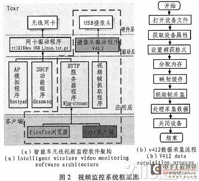
As shown in Figure 1(b), the main components of the lower computer are shown in the figure. The intelligent vehicle video monitoring system uses the Tianqian Technology Cortex-A8 X210 development board as the development platform. Its processor uses the Samsung S5pv210 chip. The S5PV210 uses the ARMCortexTM-A8 core, ARM V7 instruction set, and the main frequency can reach 1 GHZ, 64/32-bit internal bus structure, 32/32kB data/instruction level 1 cache, 512 kB level 2 cache, and can achieve a high-performance computing capability of 2000DMIPS (2 billion instructions per second). The wifi module mainly completes the networking and remote control functions of the lower computer and the upper computer; at the same time, the development board is also equipped with sensors for detecting temperature and harmful gases, so it can perform risk assessment and early warning of the detection environment.
2 Design and implementation of functional modules of intelligent vehicle wireless video surveillance system
2.1 Design of software architecture for smart car video surveillance system
The Linux development platform adopted by the intelligent vehicle video surveillance system is a multi-user and multi-tasking operating system with good openness. It follows the world standard specifications, especially the international standards for the interconnection of open systems. With a complete built-in network, Linux is superior to other operating systems in terms of communication and network functions. The system image acquisition is to capture the video through the ARM-Linux dispatching V4L2 driver. V4L2 is the basis of the Linux imaging system and embedded imaging. It is a set of APIs in the Linux kernel that support imaging devices. The application of Linux in multimedia is currently a very popular research field, and the most critical technology is Linux's V4L2. Most of the traditional ARM-based remote video surveillance uses the MFC module integrated in the CPU to perform hardware compression and decoding on the data collected by the V4L2 interface. Hardware decoding requires hardware to have hardware decoding modules, related driver cooperation, suitable playback software, and correct settings for the playback software. Without any of them, the hardware decoding function cannot be enabled. Due to the above problems, this article uses an open source software mjpeg-stream network video server instead of MFC. mjpg_streamer is an open source network video server that requires very little CPU and memory resources to work. Most of the encoding work is done by the camera, which is very suitable for use in embedded environments.
2.1.1 Transplantation of network video server mjpeg-strearm
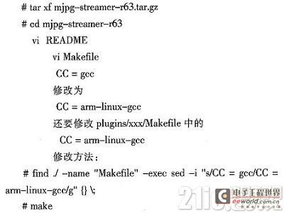
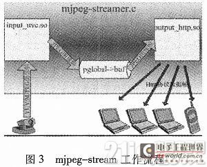
For the compression and decoding of the data collected from the v4l2 interface, we chose the network video server mjpeg-stream. Another reason why I did not choose the MFC module integrated in the CPU is that the remote wireless video monitoring system of the intelligent car designed this time must support remote web interface access operations. If MFC is selected, it is necessary to transplant embedded web servers such as Boa to perform remote access. The video stream collected by the MFC module also needs to use open source software and function libraries on the PC side to realize video playback, but the mjpeg-stream network video server can save these steps because mjpeg-stream supports remote web access. This reduces the workload and complexity of development. The following is the transplantation and compilation of mjpeg-stream. Figure 3 shows the process of mjpeg-stream for data collection and transmission.
2.1.2 Design of data receiving and display module of smart car video surveillance system
As shown in Figure 2(a) and Figure 3, there are two servers inside the mjpeg-stream network video server, the http server and the video frame capture server. The http server sends the image frames collected by the video frame capture server to the client in the form of Http protocol data frames. Therefore, there are two parts to be completed in the programming work: one is to read the Http protocol data frame from the http server (the Http protocol data frame consists of the header information related to the http protocol and the image data frame (jpeg format)), and the other is to extract the image data frame from the Http protocol data frame. The GUI interface of this article uses Qt to design and implement the client and web client of C/S and B/S architecture. The display of the video interface of the intelligent vehicle monitoring system consists of two parts: one is to receive the transmitted data through the TCP protocol (implemented by socket programming), and the other is the display of the video image on the client. The design flow chart of the client software is shown in Figure 4.
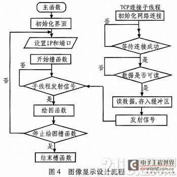
Since we extract the image data frame from the HTTP protocol data frame through programming and display it on the client to achieve real-time video monitoring, we can start another thread in the main function to complete the image capture function, that is, the photo taking function. This provides data basis for the intelligent car to explore and analyze the unknown space.
2.2 Design of Wi-Fi Function Module
Another core of the smart car wireless video surveillance system developed this time is the development of the wifi module. The two most basic elements of a wireless network are: one is an AP (Access Point) and the other is a wireless network card. The above two points can form a simple wireless network. Because we want to remotely control the smart car through the client on the smart terminal and PC, how to turn the smart car into a mobile wifi hotspot is the focus of our design this time.
A core content of embedded development is how to use various open source software to complete the functions we need on limited hardware resources. So turning a smart car into a mobile wifi hotspot requires the following steps:
1) Download and install the driver of the rtl8188eu wireless chip; 2) Use the hostapd open source software to switch the wireless network card to master mode and simulate the AP (router) function; 3) Use the dnsmasq open source software to dynamically assign IP to the client. The main steps to implement the process on the development board are as follows:
#insmod/home/wifi/8188eu.ko
# ifconfig wlan0 192.168.137.1 (enable wireless network card)
# ./hostapd rtl_hostapd_2G.conf-B (simulate AP function)
#./dnsmasq—C dnsmasq.conf (enable DNS and DHCP functions)
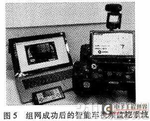
By transplanting and developing the above open source software, the smart car can be turned into a mobile WiFi hotspot, and the smart car wireless video monitoring system can be controlled through smart terminals such as mobile phones. Figure 5 shows the working status of the smart car wireless video monitoring system after successful networking.
3 Conclusion
This paper implements a smart car wireless video monitoring system with s5pv210 as the core processor. This system can use smart terminals to control the smart car wireless video monitoring system through wifi, or it can be controlled through wired connections. The smart car can not only monitor and take pictures in real time, but also detect the surrounding environment through the temperature sensor and harmful gas sensor on the development board. Therefore, it can be used in harmful and dangerous occasions such as urban security, national defense and space detection. It also has certain research value for the future development of smart cars.
Previous article:Design of image acquisition and transmission system based on STM32F107
Next article:Brief Analysis of STM32 Official Firmware Library
Recommended ReadingLatest update time:2024-11-16 16:33


 Professor at Beihang University, dedicated to promoting microcontrollers and embedded systems for over 20 years.
- Innolux's intelligent steer-by-wire solution makes cars smarter and safer
- 8051 MCU - Parity Check
- How to efficiently balance the sensitivity of tactile sensing interfaces
- What should I do if the servo motor shakes? What causes the servo motor to shake quickly?
- 【Brushless Motor】Analysis of three-phase BLDC motor and sharing of two popular development boards
- Midea Industrial Technology's subsidiaries Clou Electronics and Hekang New Energy jointly appeared at the Munich Battery Energy Storage Exhibition and Solar Energy Exhibition
- Guoxin Sichen | Application of ferroelectric memory PB85RS2MC in power battery management, with a capacity of 2M
- Analysis of common faults of frequency converter
- In a head-on competition with Qualcomm, what kind of cockpit products has Intel come up with?
- Dalian Rongke's all-vanadium liquid flow battery energy storage equipment industrialization project has entered the sprint stage before production
- Allegro MicroSystems Introduces Advanced Magnetic and Inductive Position Sensing Solutions at Electronica 2024
- Car key in the left hand, liveness detection radar in the right hand, UWB is imperative for cars!
- After a decade of rapid development, domestic CIS has entered the market
- Aegis Dagger Battery + Thor EM-i Super Hybrid, Geely New Energy has thrown out two "king bombs"
- A brief discussion on functional safety - fault, error, and failure
- In the smart car 2.0 cycle, these core industry chains are facing major opportunities!
- The United States and Japan are developing new batteries. CATL faces challenges? How should China's new energy battery industry respond?
- Murata launches high-precision 6-axis inertial sensor for automobiles
- Ford patents pre-charge alarm to help save costs and respond to emergencies
- New real-time microcontroller system from Texas Instruments enables smarter processing in automotive and industrial applications
- How UWB calculates location
- [Repost] When choosing a finished power module, should you use an isolated or non-isolated power solution?
- Qorvo Q&A on Connectivity: Reducing Wi-Fi Interference
- What device is used to heat the chip on the motherboard in low temperature outdoor conditions?
- CB5654 Development Board Evaluation 3 - Building a Development Environment
- Two-phase brushless DC motor speed control system based on DSP and CPLD
- 15. [Learn LPC1768 library functions]
- Anxinke PB-02 module review (1) - Compilation environment construction & appearance display
- 3. [Record] Two library files that must be installed by the GCC compiler
- Analysis of the characteristics of IQ modulators

 Network Operating System (Edited by Li Zhixi)
 Arduino UNO R4 WiFi Engineering Code


 京公网安备 11010802033920号