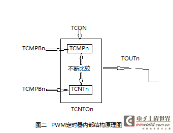
Although there are many timers, the working principles are the same. You only need to understand the working principle of one timer. For a certain timer, its internal structure schematic diagram is shown in Figure 2. The cache registers TCMPBn and TCNTBn are used to cache the comparison value and initial value of timer n; TCON is used to control the start and end of the timer; the current count value of the timer is obtained by reading the register TCNTOn.
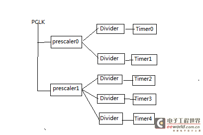
Among them: prescaler value = 0~255 (its value is set by the TCFG0 register, as shown in the figure below)
| TCFG0 | Bit | describe | Initial Value |
| reserve | [31:24] | 0x00 | |
| Dead zone length | [23:16] | These 8 bits determine the length of the dead zone. The unit time of the dead zone length is equal to the unit time of timer 0. |
0x00 |
| Prescaler 1 | [15:8] | These 8 bits determine the pre-scaler value of timer 2, 3, and 4. | 0x00 |
| Prescaler 0 | [7:0] | These 8 bits determine the pre-scaler value of timer 0 and 1. | 0x00 |
| |
Bit | describe | Initial Value |
| Timer 0 computer buffer register | [15:0] | Set compare buffer value for Timer0 | 0x00000000 |
| |
Bit | describe | Initial Value |
| Timer 0 count buffer register | [15:0] | Set count buffer value for Timer 0 | 0x00000000 |
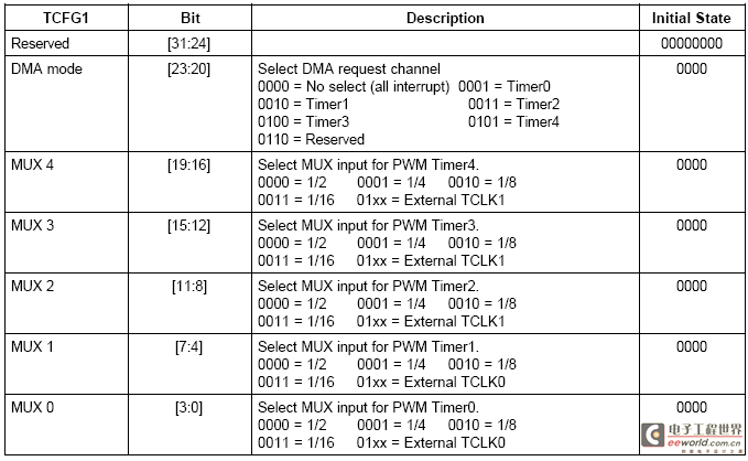
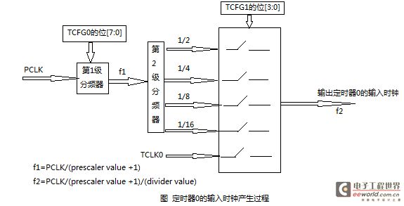
Example 1: Combined with the above explanation, we can know that the input clock of timer 0 is obtained by dividing the PCLK. The figure below shows its generation process. -------------------------------------Dividing line--------------------------------------------------- Analysis: In the previous question, two timer configuration registers TCFG1 and TCFG0 appear. Among them, the TCFG0 configuration register controls the division coefficient of the first-level divider prescaler, and the TCFG1 configuration register controls the multi-way selection switch to select the division coefficient of the second-level divider divider. The details are shown in the following figure: -----------------------------------------Dividing line----------------------------------------------------- -----------------------------------------Dividing line--------------------------------------------------- Example 2: PCLK is 50MHz, please set an appropriate division coefficient to make the input clock of timer 0 62.5kHz. Answer: Knowing that PCLK is 50MHz, 50MHz/62.5kHz=800, that is, PCLK needs to be divided by 800. Therefore, the frequency division coefficient of the first-stage frequency divider is 100, and the frequency division coefficient of the second stage is 8 to meet the requirements. Finally, you only need to write the frequency division coefficient to the corresponding bit in the timer control register. The code is as follows: 1 rTCFG0&=~(0xFF); clear the lower 8 bits of TCFG0 2 rTCFG0|=99; because the frequency division coefficient = prescaler+1, that is, prescaler+1=100, so prescaler value=99 3 rTCFG1&=~(0xF); clear the lower 4 bits of TCFG1

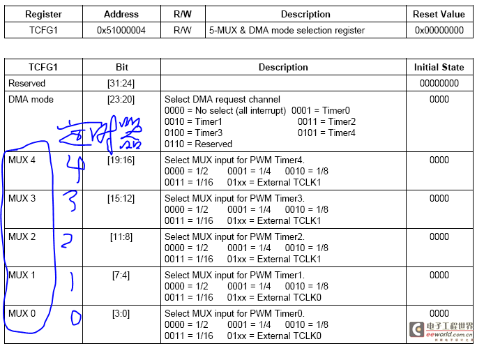
4
Previous article:S3C2440 system clock
Next article:Parameter passing under ARM
Recommended ReadingLatest update time:2024-11-16 14:46
Linux-4.9.2 kernel porting on mini2440 (Part 2) Ubuntu compilation environment setup (Part 2)

2.1 Install arm-linux-compiler The compiler can be installed automatically in Ubuntu using the apt command, or it can be installed manually by downloading an independent installation package. Both installation methods can compile the kernel, and different versions of arm-linux-gcc can coexist in the system. This artic
[Microcontroller]

Linux-2.6.32 transplanted SD card driver on mini2440 development board
Editor: This driver is quite complex, so let's port it first and analyze it later.
SD card driver transplantation
1 Register SD device driver in the kernel
Linux-2.6.32.2 already comes with the SD card driver for the S3C2440 chip. We only need to add the SD platform device structure to the initializati
[Microcontroller]
mini2440 i2c device support
Kernel version: linux-2.6.32.2 Experimental platform: mini2440 1. Add support for master devices The i2c master controller is also a device, but it is virtualized as a platform device in the kernel. The platform device has been defined in the kernel in plat-s3c/dev-i2c0.c: static struct resource s3c_i2c_resource = {
[Microcontroller]
STM32 Timer PWM_Output

The pulse width modulation mode can generate a signal with a frequency determined by the TIMx_ARR register and a duty cycle determined by the TIMx_CCRx register.
The following is an example of PWM mode 1. The PWM signal reference OCxREF is high when TIMx_CNT
Library function STM32F10x_StdPeriph_Lib_V3.3.0\Proje
[Microcontroller]

MSP430F149 TIMER_A (I)——16-bit timing counter
TIMER_A has four optional clock sources. For convenience, ACLK and SMCLK are generally selected. A time base is generated through a frequency divider. Its structure diagram is as follows:
TIMER_A has three timing/counting modes:
(1). Incremental counting mode: Counting cycle: TAR increases from 0 to TAC
[Microcontroller]
u-boot2011.12 transplantation on mini24402
The error in the transplantation 1 of u-boot2011.12 on mini2440 was found after checking the source code that it was caused when NOR Flash support was started. Considering that NOR Flash support is not needed, NOR FLASH support is removed. 1. Add macro definition in mini2440.h #define CONFIG_SYS_NO_FLASH Used to tur
[Microcontroller]
PIC32MZ tutorial -- 32-bit Timer
The microcontroller is PIC32MZ2048ECH144 on the PIC32MZ EC Starter Kit. This microcontroller has four 32-bit synchronous timers are available by combining Timer2 with Timer3, Timer4 with Timer5, Timer6 with Timer7, and Timer8 with Timer9. The 32-bit timers can operate in one of three modes: •Synchronous internal 3
[Microcontroller]
MINI2440 bare metal experiment: SDRAM
Programming This experiment will initialize SDRAM and copy the program itself to SDRAM and then jump to SDRAM to continue executing the pipeline. The modifications are still based on the last program. The files that need to be modified this time include "start.S" and "Makefile". The contents of the modified files are
[Microcontroller]
- Popular Resources
- Popular amplifiers
Recommended Content
Latest Microcontroller Articles
He Limin Column
Microcontroller and Embedded Systems Bible
 Professor at Beihang University, dedicated to promoting microcontrollers and embedded systems for over 20 years.
MoreSelected Circuit Diagrams
MorePopular Articles
- Innolux's intelligent steer-by-wire solution makes cars smarter and safer
- 8051 MCU - Parity Check
- How to efficiently balance the sensitivity of tactile sensing interfaces
- What should I do if the servo motor shakes? What causes the servo motor to shake quickly?
- 【Brushless Motor】Analysis of three-phase BLDC motor and sharing of two popular development boards
- Midea Industrial Technology's subsidiaries Clou Electronics and Hekang New Energy jointly appeared at the Munich Battery Energy Storage Exhibition and Solar Energy Exhibition
- Guoxin Sichen | Application of ferroelectric memory PB85RS2MC in power battery management, with a capacity of 2M
- Analysis of common faults of frequency converter
- In a head-on competition with Qualcomm, what kind of cockpit products has Intel come up with?
- Dalian Rongke's all-vanadium liquid flow battery energy storage equipment industrialization project has entered the sprint stage before production
MoreDaily News
- Allegro MicroSystems Introduces Advanced Magnetic and Inductive Position Sensing Solutions at Electronica 2024
- Car key in the left hand, liveness detection radar in the right hand, UWB is imperative for cars!
- After a decade of rapid development, domestic CIS has entered the market
- Aegis Dagger Battery + Thor EM-i Super Hybrid, Geely New Energy has thrown out two "king bombs"
- A brief discussion on functional safety - fault, error, and failure
- In the smart car 2.0 cycle, these core industry chains are facing major opportunities!
- The United States and Japan are developing new batteries. CATL faces challenges? How should China's new energy battery industry respond?
- Murata launches high-precision 6-axis inertial sensor for automobiles
- Ford patents pre-charge alarm to help save costs and respond to emergencies
- New real-time microcontroller system from Texas Instruments enables smarter processing in automotive and industrial applications
Guess you like
- Several concepts of ARM simulation JTAG/J-LINK/ULINK/ST-LINK and their differences
- [NXP Rapid IoT Review] Hello Phased Experience
- STM32F103 and MM32F103 experience
- SPI ASF issue on Atmel ATSAM3X8E
- TouchGFX Design + Make a Rubik's Cube (2)
- Electronic digital alarm clock based on GD32E231
- New version of UFUN learning board information
- 【NXP Rapid IoT Review】 The first test program
- How to Reduce Ripple in a PWM DAC in a Microprocessor
- Interrupt-Based Ambient Light and Environment Sensor Node Reference Design for Sub-1 GHz Networks

 西门子S7-12001500 PLC SCL语言编程从入门到精通 (北岛李工)
 FollowMe Issue 3 - Plant Care Monitor - MicroPython - XiaoESP32C3
 Example interpretation of 51 single chip microcomputer complete learning and application


 京公网安备 11010802033920号