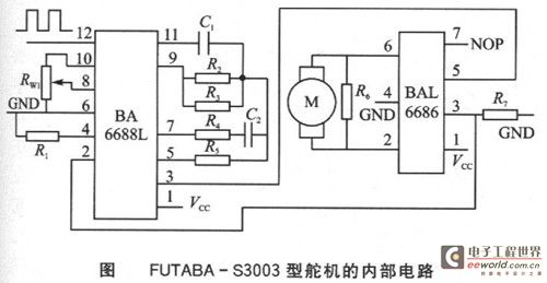
The working principle of the servo is as follows: the PWM signal enters the signal demodulation circuit BA66881 from the receiving channel. It is demodulated at the 12th pin to obtain a DC bias voltage. The DC bias voltage is compared with the voltage of the potentiometer, and the voltage difference is output by the 3rd pin of BA6688. The output is sent to the motor driver integrated circuit BA6686 to drive the motor forward and reverse. When the motor speed is constant, the potentiometer R is driven by the cascade reduction gear to rotate until the voltage difference is 0 and the motor stops. The control signal of the servo is a PWM signal, which changes the position of the servo by changing the duty cycle.

Control method of steering gear
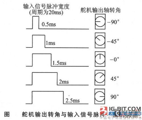
The power line and ground line are used to provide the energy required by the DC motor and control circuit inside the servo . The voltage is usually between 4 and 6V, and 5V is generally used. Note that the power supply to the servo should be able to provide sufficient power. The input of the control line is a periodic square wave pulse signal with adjustable width. The period of the square wave pulse signal is 20 ms (that is, the frequency is 50 Hz). When the pulse width of the square wave changes, the angle of the servo shaft changes, and the angle change is proportional to the change in pulse width. The relationship between the output shaft angle of a certain type of servo and the pulse width of the input signal can be expressed as 3.

Hardware circuit design of servo controller
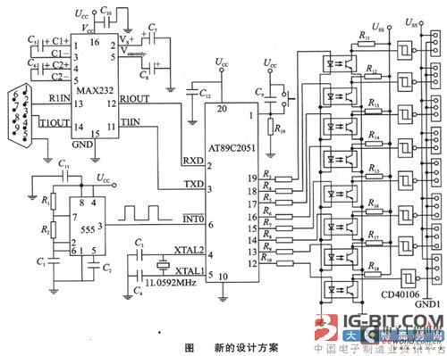
From the above control method of the steering gear angle, it can be seen that the control signal of the steering gear is actually a square wave signal (PWM) with variable width. The square wave signal can be generated by FPGA, analog circuit or single-chip microcomputer. The cost of using FPGA is high, and the circuit is more complicated if it is implemented by analog circuit, which is not suitable for multi-channel output. Generally, a single-chip microcomputer is used as the controller of the steering gear. At present, there are many schemes using single-chip microcomputer as the steering gear controller, and PWM can be realized by using the timer interrupt of the single-chip microcomputer. This scheme divides the 20ms periodic signal into two timing interrupts to complete: one timing to realize the high-level timing Th; one timing to realize the low-level timing T1. The time values of Th and T1 change with the change of pulse width, but Th+T1=20ms. The advantage of this method is that the PWM signal is completely realized by the interrupt of the internal timer of the single-chip microcomputer, and no peripheral hardware needs to be added. The disadvantage is that the PWM signal in one cycle must be completed by two interrupts, and the calculation of the timing values of the two interrupts is more troublesome; in order to meet the 20ms cycle, the frequency of the single-chip microcomputer crystal oscillator must be reduced; and multi-channel output cannot be realized. The implementation scheme of single-chip microcomputer + 8253 counter can also be used. In this scheme, the microcontroller generates counting pulses (or the external circuit generates counting pulses) and provides them to 8253 for counting. The microcontroller gives the counting comparison value of 8253 to change the output pulse width. The advantage of this scheme is that it can realize multi-channel output and the software design is relatively simple; the disadvantage is that it needs to add an 8253 counter, which increases the hardware cost. Based on the above two microcontroller servo control schemes, this paper proposes a new design scheme, as shown in Figure 4.

The servo controller of this scheme is based on the AT89C2051 ($0.5940) single-chip microcomputer as the core, and the oscillator composed of 555 is used as the timing reference. The single-chip microcomputer generates PWM signals by counting the pulse signals generated by the 555 oscillator. The single-chip microcomputer in this controller can generate 8 channels of PWM signals, which are output by the P1.0~Pl.7 (12~19 pins) ports of the AT89C2051. The output 8-channel PWM signals are transmitted to the next level circuit through optocoupler isolation. Because the signal is inverted during the transmission process through the optocoupler, the signal from the optocoupler must be inverted again through the inverter. After the square wave signal is transmitted through the optocoupler, the leading and trailing edges will be distorted, so the inverter uses the CD40106 ($0.1125) Schmidt inverter to shape the signal transmitted by the optocoupler to generate a standard PWM square wave signal. During the experiment, the author found that the servo absorbs a large current from the power supply during operation. If the servo and the single-chip controller share a power supply, the servo will cause greater interference to the single-chip. Therefore, the servo and the single-chip controller are powered by two power supplies, which are not shared by the same ground and isolated by optical couplers. In addition, the power supply for the servo is preferably a switching power supply with a large output power. The servo controller occupies the SCI serial port of the single-chip microcomputer. The serial port is used to receive the control command sent by the host computer to adjust the pulse width of the output signal of each channel. MAX232 ($2.0686) is a level converter, which converts the RS232 ($780.5000) level of the host computer into TTL level.
The principle of realizing multi-channel PWM signals

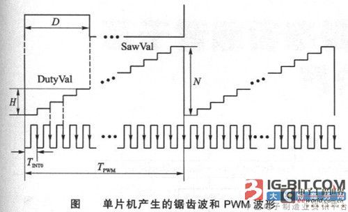
In analog circuits, PWM pulse signals can be obtained by comparing the DC level with the sawtooth wave signal. In a single-chip microcomputer, a sawtooth wave can be realized by adding 1 to an integer variable, as shown in Figure 5. Assume that an integer variable SawVal is set in the single-chip microcomputer program, and its value range is O~N. The external counting clock signal generated by the 555 oscillation circuit is input to the INTO pin of the AT89C2051. Whenever the external counting clock pulse falls, the single-chip microcomputer generates an external interrupt and executes the interrupt service program of the external interrupt INT0. Every time an external interrupt is generated, an addition operation is performed on SawVal. If SawVal has reached the maximum value N, SawVal is cleared to 0. The change pattern of the SawVal value is equivalent to a sawtooth wave, as shown in Figure 5. If another integer variable DutyVal is set in the single-chip microcomputer program, its value range is O~N. Whenever SawVal is cleared to 0, DulyVal reads the pulse width coefficient value from the control command sent by the host computer, for example, H (0≤H≤N). If DutyVal≥SawVal, the corresponding port outputs a high level; if DutyVal
Previous article:What is the delay of 51 single chip microcomputer
Next article:Analyzing the issues related to precise delay of microcontrollers
Recommended ReadingLatest update time:2024-11-23 02:55

- Popular Resources
- Popular amplifiers
-
 Learning MCU Technology from Scratch (Liu Jianqing)
 -
 Chip Manufacturing: A Practical Tutorial on Semiconductor Process Technology (Sixth Edition)
 -
 Wireless doorbell alarm based on AT89C2051 single chip microcomputer
 -
 Introduction to the classification, application, composition and model of phase-locked loop
- Naxin Micro and Xinxian jointly launched the NS800RT series of real-time control MCUs
- How to learn embedded systems based on ARM platform
- Summary of jffs2_scan_eraseblock issues
- Application of SPCOMM Control in Serial Communication of Delphi7.0
- Using TComm component to realize serial communication in Delphi environment
- Bar chart code for embedded development practices
- Embedded Development Learning (10)
- Embedded Development Learning (8)
- Embedded Development Learning (6)
 Professor at Beihang University, dedicated to promoting microcontrollers and embedded systems for over 20 years.
- Intel promotes AI with multi-dimensional efforts in technology, application, and ecology
- ChinaJoy Qualcomm Snapdragon Theme Pavilion takes you to experience the new changes in digital entertainment in the 5G era
- Infineon's latest generation IGBT technology platform enables precise control of speed and position
- Two test methods for LED lighting life
- Don't Let Lightning Induced Surges Scare You
- Application of brushless motor controller ML4425/4426
- Easy identification of LED power supply quality
- World's first integrated photovoltaic solar system completed in Israel
- Sliding window mean filter for avr microcontroller AD conversion
- What does call mean in the detailed explanation of ABB robot programming instructions?
- STMicroelectronics discloses its 2027-2028 financial model and path to achieve its 2030 goals
- 2024 China Automotive Charging and Battery Swapping Ecosystem Conference held in Taiyuan
- State-owned enterprises team up to invest in solid-state battery giant
- The evolution of electronic and electrical architecture is accelerating
- The first! National Automotive Chip Quality Inspection Center established
- BYD releases self-developed automotive chip using 4nm process, with a running score of up to 1.15 million
- GEODNET launches GEO-PULSE, a car GPS navigation device
- Should Chinese car companies develop their own high-computing chips?
- Infineon and Siemens combine embedded automotive software platform with microcontrollers to provide the necessary functions for next-generation SDVs
- Continental launches invisible biometric sensor display to monitor passengers' vital signs
- Power consumption of monochrome LCD screen
- Driving of light-emitting diodes for lighting and dedicated driving power converter
- Some problems encountered when using spartan6 PLL IP Core
- Books purchased with E-coins
- RIID emits a weak signal
- How to test wire length using LOTO oscilloscope TDR method?
- Help
- [ST Motor Review] 1. Familiarity with the Development Kit
- I would like to ask if anyone has disassembled this kind of antenna?
- Advanced MCU Serial Port Programming

 Learning MCU Technology from Scratch (Liu Jianqing)
 Wireless doorbell alarm based on AT89C2051 single chip microcomputer


 京公网安备 11010802033920号