Lead-acid batteries have the advantages of low price, reliable power supply, and stable voltage. They are widely used in communications, railways, transportation, electricity, petroleum, national defense, and industrial and agricultural production departments. In traditional charging technology, commonly used constant voltage charging, constant voltage current limiting charging, constant current charging and other modes are all controlled by workers during the charging process. Since the charging technology cannot adapt to the special requirements of maintenance-free batteries, it seriously affects the life of the battery. A large number of maintenance-free batteries are scrapped after a few years of use, causing huge economic losses. The new intelligent charger system introduced in this article solves the technical key of dynamically tracking the acceptable charging current curve of the battery, forming a unique series of intelligent chargers, improving the charging quality and efficiency. Charging workers only perform auxiliary work, breaking a new path for charging technology and charging equipment.
1 Hardware Part
During the battery charging and discharging process, various control rules can be selected, such as constant current, constant voltage, trickle current, charging and discharging time, and termination voltage. The whole system is divided into two layers, the lower layer is the execution layer, and the upper layer is the control layer.
1.1 Node layer
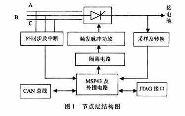
The three-phase bridge fully controlled rectifier bridge technology is used to realize the charging and discharging conversion. The triggering of the thyristor is completed by MSP430. It is planned to use double narrow pulse triggering to reduce the output power of the triggering device. The core of the lower layer lies in the control of MSP430. MSP430F135 is a 16-bit single-chip microcomputer of the Flash series recently launched by TI. It has a built-in 12-bit A/D converter, a serial communication interface, an integrated JTAG interface, a built-in Flash memory, a watchdog timer, and two 16-bit timers, which can realize counting, timing generation, PWM and other functions. And through the processing of the stack, the interrupt and subroutine call level is unlimited, and it has a nested interrupt structure, that is, the high-level interrupt program can be interrupted by the low-level interrupt request. When the interrupt request occurs at the same time, it is processed according to the priority level. The 12-bit A/D is used to collect current and voltage values as feedback variables for closed-loop control. The processed feedback variables are compared with the set values, and the trigger angle is determined according to certain control rules. The microcontroller directly gives a trigger signal to open the thyristor. The control accuracy can reach 2.5‰. The current and voltage acquisition adopts differential mode amplification technology. The circuit is simple, easy to implement, and has high feedback accuracy. The single-channel structure diagram is shown in Figure 1.

1.2 The control layer
realizes the distributed control of the control system. The main task of the middle layer is to collect the data of multiple lower computers. The middle layer is based on the ATmega16 microcontroller, which is an 8-bit microcontroller compatible with the 51 series and easy to expand peripherals. The lower computer data is uploaded to the non-volatile large-capacity memory (Flash) DA28F640 of this layer through the communication interface. The human-machine interface LCD liquid crystal display and keyboard input are added to this layer, and the operator directly controls the lower computer at this layer. This system can also be networked and connected to a computer. The operator can monitor and manage the lower computer through a PC.
2 Software part
This system is designed in assembly language and modular program structure. It consists of several modules such as the main program module, data acquisition module, data processing module, timing pulse emission module and communication module. The program first determines the execution command, and then transfers to the condition setting subroutine. For example, for the constant current charging command, the program first assigns the command end conditions such as setting the current and termination time to the judgment variables, and then sets the Boolean value of these variables to true. In this way, various charging and discharging commands are simplified to direct condition judgment by the main loop. The overall program structure is compact, simple, easy to understand, and easy to design, debug, maintain and transplant.
2.1 Data acquisition/processing
The data acquisition of this system adopts a differential amplifier circuit to directly introduce voltage and current signals from both ends of the battery. The amplifier OP07 is selected. The analog to digital conversion part is completed by the built-in A/D converter of MSP430. The A/D conversion is started in the main loop. After the conversion is completed, the interrupt program stores the converted value in the specified register and waits for all conversions to be processed. The conversion end flag is set to prevent repeated startup. Due to the existence of various interferences on site, the data obtained has a certain error. In order to make the conversion result more accurate, and considering the sensitivity of the system, each input signal can be sampled about 4 times, and digital filtering is used in processing, and the arithmetic mean method is used. The arithmetic mean method is suitable for filtering general signals with random interference, especially for the situation where the signal itself fluctuates around a certain value.
In the application, multiple algorithms can also be used in combination according to the actual situation of the measured parameters and the data rules obtained to obtain a more effective filtering effect. The processed value is first compared with the set value to obtain the difference, and then the relationship is:

Where: Ud is the effective value of the secondary phase voltage of the transformer;
U2L is the effective value of the secondary line voltage of the transformer.
The experiment results in the adjustment relationship between the voltage and current difference corresponding to the degree, and then the relationship between the degree and time is converted into a time parameter. After converting the voltage and current difference into the time difference, the time difference is added (charging) or subtracted (discharging) from the original set value, so as to dynamically adjust the angle, further dynamically adjust the voltage and current values, and maintain the voltage and current with a certain acceptable curve change. Since the system can continuously collect the current and voltage values fed back, and dynamically adjust the control quantity at any time according to the situation, the system can keep up with the changes in current and voltage at any time and take corresponding measures, avoiding the possibility of excessive current during the charging/discharging process, and making the current curve change smoothly. [page]
2.2 Pulse trigger program
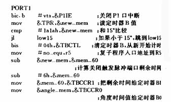
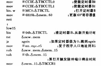
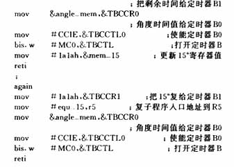
The P1 port of MSP430 has an external interrupt working mode. Any two phases of the three-phase power are led out through the transformer and connected to the P1 port through the comparator. When the two phases are exchanged, the P1 port will cause an interrupt, which can accurately determine the position of the switching point of the two phases. After determining the position of the switching point, the timer is turned on in the P1 port interrupt program, and the time value converted from the voltage is paid to the 16-bit register of the timer. The timer generates an interrupt after the trigger angle time, and the pin of the corresponding trigger pulse is turned on in the timer interrupt program. According to the rule, the pulse ends after 15°, and then after 45°, the next trigger pin is turned on. After one cycle (360°), the sampled voltage or current re-determines the trigger angle and resets the register of the timer. 2.3 Upper-level program The upper-level program mainly consists of two parts: the human-machine interface part and the communication part. The human-machine interface includes two parts: keyboard control and display. In the program, various control rules and control programs are compiled using the keyboard. The DA28F640 can be divided into several areas, with each node in the lower layer corresponding to one area. The corresponding charging and discharging program and the field data transmitted from the lower layer are stored in the corresponding area. A small font library is established inside the single-chip microcomputer to store the characters to be displayed, ensuring that the LCD screen can dynamically display the current voltage, current, time and other values.3 ConclusionThis system has a high degree of automation, which greatly improves production efficiency; the human-machine interface is friendly and easy to operate and manage. The operator only needs to compile the control program at the control layer, and the system is responsible for transmitting the program to each node, and each node operates independently without guarding in the middle, realizing the full automation of the equipment. The changes in current and voltage during the working process are automatically adjusted by the system. In the case of power failure, the system will automatically save the field data, realizing the intelligence of the system.


Previous article:Design of low power consumption temperature detector based on single chip microcomputer
Next article:Application of RS-485 bus communication system
Recommended ReadingLatest update time:2024-11-16 14:58


- Popular Resources
- Popular amplifiers
 Professor at Beihang University, dedicated to promoting microcontrollers and embedded systems for over 20 years.
- Innolux's intelligent steer-by-wire solution makes cars smarter and safer
- 8051 MCU - Parity Check
- How to efficiently balance the sensitivity of tactile sensing interfaces
- What should I do if the servo motor shakes? What causes the servo motor to shake quickly?
- 【Brushless Motor】Analysis of three-phase BLDC motor and sharing of two popular development boards
- Midea Industrial Technology's subsidiaries Clou Electronics and Hekang New Energy jointly appeared at the Munich Battery Energy Storage Exhibition and Solar Energy Exhibition
- Guoxin Sichen | Application of ferroelectric memory PB85RS2MC in power battery management, with a capacity of 2M
- Analysis of common faults of frequency converter
- In a head-on competition with Qualcomm, what kind of cockpit products has Intel come up with?
- Dalian Rongke's all-vanadium liquid flow battery energy storage equipment industrialization project has entered the sprint stage before production
- Allegro MicroSystems Introduces Advanced Magnetic and Inductive Position Sensing Solutions at Electronica 2024
- Car key in the left hand, liveness detection radar in the right hand, UWB is imperative for cars!
- After a decade of rapid development, domestic CIS has entered the market
- Aegis Dagger Battery + Thor EM-i Super Hybrid, Geely New Energy has thrown out two "king bombs"
- A brief discussion on functional safety - fault, error, and failure
- In the smart car 2.0 cycle, these core industry chains are facing major opportunities!
- The United States and Japan are developing new batteries. CATL faces challenges? How should China's new energy battery industry respond?
- Murata launches high-precision 6-axis inertial sensor for automobiles
- Ford patents pre-charge alarm to help save costs and respond to emergencies
- New real-time microcontroller system from Texas Instruments enables smarter processing in automotive and industrial applications
- Security Technology System of Wireless WLAN
- It is found that the OPAMP of STM32G474 cannot be internally connected to ADC4
- In-depth understanding of C language function parameters as pointers
- EEWORLD University Hall ---- The first stop of the ADI Road theme tour of Shijian: Industrial Automation
- AD20 Installation Issues
- Are there any commonly used solutions recommended for converting 0-10V to PWM?
- Looking for C8051F58x/F59x IDE?
- 9. [Learning LPC1768 library functions] Clkout experiment
- DSP28335 eCAP module capture pulse problem
- CC1310 Two-wire Serial Bootloader Solution

 Battery Management Systems for Electric and Hybrid Vehicles


 京公网安备 11010802033920号